Safety Bus Manual — P/N LS10177-000HI-E:B 02/21/2019 34
SB-NCM Module System Components
NOTE: During the startup sequence, the yellow and red LEDs blink 3 times, then the seven red
LEDs L1-L7 will go on for 2 seconds to indicate the module address in binary format (L1=1, L2=2,
L3=4, L4=8, L5=16, L6=32, L7=64). At this point, the eight yellow LEDs L1-L8 will begin to blink
rapidly until the module is configured by the panel.
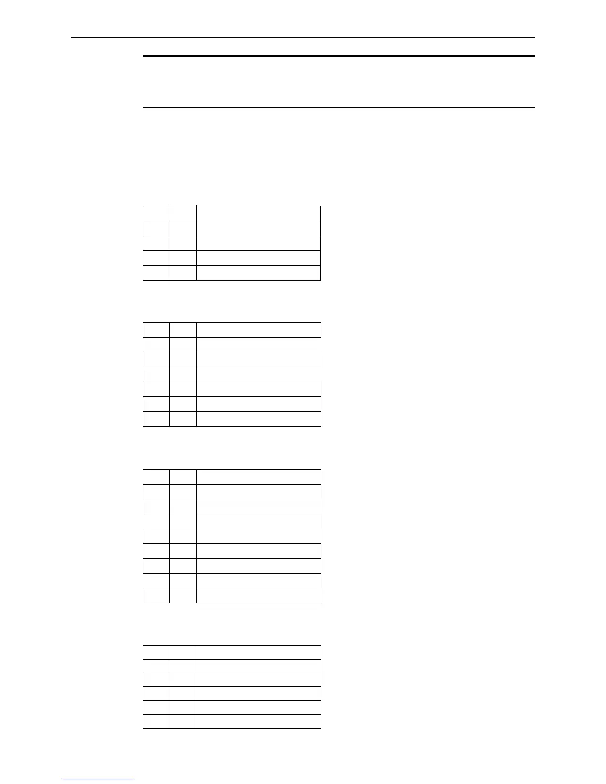
3.6.3 Connections
The SB-NCM module features the following connectors:
Terminal Block TB1
This terminal block supplies power to the module.
Terminal Block TB2
This terminal block connects the two ring communication links.
Terminal Block TB3
This terminal block is used to connect channels 1, 2, 3, and 4.
Terminal Block TB4
This terminal block is used to connect channels 5, 6, 7 and 8.
Pin Tag Function
1 +V 24VDC Power supply positive
2 +V 24VDC Power supply positive
3 -V 24VDC Power supply negative
4 -V 24VDC Power supply negative
Pin Tag Function
1 -LK1 Link-1 Negative
2 +LK1 Link-1 Positive
3 SLK1 Link-1 Screen
4 -LK2 Link-2 Negative
5 +LK2 Link-2 Positive
6 SLK2 Link-2 Screen
Pin Tag Function
1 +L1 CH-1 line input positive
2 -L1 CH-1 line input negative
3 +L2 CH-2 line input positive
4 -L2 CH-2 line input negative
5 +L3 CH-3 line input positive
6 -L3 CH-3 line input negative
7 +L4 CH-4 line input positive
8 -L4 CH-4 line input negative
Pin Tag Function
1 +L5 CH-5 line input positive
2 -L5 CH-5 line input negative
3 +L6 CH-6 line input positive
4 -L6 CH-6 line input negative
5 +L7 CH-7 line input positive
 Loading...


