Safety Bus Manual — P/N LS10177-000HI-E:B 02/21/2019 24
SB-SIM/GM Module System Components
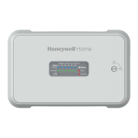
3.3 SB-SIM/GM Module
This module can control eight balanced inputs for conventional sensors with safety-related func-
tions able to control possible power voltage dispersions. All the channels can be individually reset
and are tested every 10 seconds during operation. It is used to control conventional fire detectors
and NO/NC contacts in general. This module must be used each time a local power supply is used
to power the Safety Bus modules. The first two module inputs must be configured to signal the pri-
mary and secondary power supply failure to the panel. Furthermore, the module detects ground dis-
persion of the power supply circuits and of all the secondary I/O circuits. Positive or negative
ground dispersion is indicated locally on both the module and the panel.
3.3.1 Technical Specifications
• Number of input channels:
8 individually configurable
• Wiring:
Class B Style C
• Alarm threshold:
2 programmable thresholds from 4 to 120mA
• Short-circuit threshold:
programmable from 4 to 131mA
• Open Circuit threshold:
≤1mA
• Dispersion measurement:
±0-100%
• Channel test:
performed every 30 seconds
• Power supply voltage:
24VDC
• Current consumption in stand by:
115mA
• Operating temperature:
0 to 49 °C (32 to 120.2°F)
• Storage temperature:
-55 to 85 °C (-67 to 185°F)
• Max humidity:
0-95% non condensing
• Protection rating:
IP30
• Mounting:
T35 DIN rail
• Dimensions:
53 x 167 x 100 (W x H x D mm) (2.1” x 6.6” x 4”)
• Weight:
approx. 600g (21 oz.)
• Connections:
2.5mm² removable terminal blocks
• Max. Line Impedance:
20 ft (6.096 m) in same room, in conduit
• Max. Line Impedance Input Channels 1-8:
50 ohms
• Ground Fault Impedance:
</ 500 ohms
• Max distance between two modules:
20 ft (6.096 m) in conduit

 Loading...


