Safety Bus Manual — P/N LS10177-000HI-E:B 02/21/2019 20
S81-F7011-1 Control Board System Components
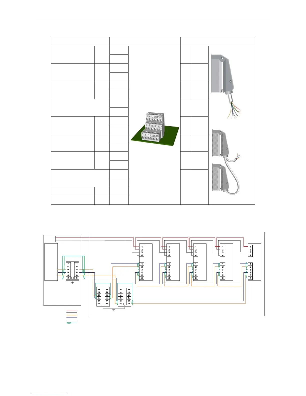
3.1.3 Connections
3.1.4 Typical Connection
Function E2004-1 Termination Multiple-wire Termination
+ Link 1 +Lk1
1
E2004-1
1 Yellow
S81/CCT8
S81/CCT8R
4
- Link 1 -Lk1
7
2 Black
10
Link 1 Screen
Sch-
Lk1
13
3 Screen
16
2
5
+ Link 2 +Lk1
8
1 Yellow
11
- Link 2 -Lk1
14
2 Black
17
Link 2 Screen
Sch-
Lk1
3
3 Screen
6
9
12
+24V (500mA max.) +24V 15
0V 0V 18
Table 3.1 Field Connections
F7011-1
V+
V-
HS-81 Panel Enclosure
Safety Bus Enclosure
SB-SIM/GM
T9003-1 SB-SIM SB-AIM SB-NCM SB-ECM
+ 24 VDC
- 24 VDC
- LK
+ LK
Ground
Shielding
*Drawing not to scale. All wiring between the Panel, the External Safety Bus Enclosures, and all separately listed regulated UL 864
power supplies (if used) should be within 20 ft (6.096 m) of each other located in the same room with cable in conduit.
T9003-1 T9003-1
TB1
TB1
TB1
Figure 3.1 Communication Ring Connections
 Loading...


