53 Safety Bus Manual — P/N LS10177-000HI-E:B 02/21/2019
Installation Wiring the Communication Ring
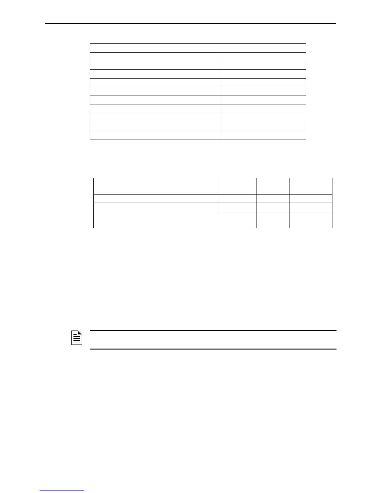
4.2.2 Recommended Cables
The following table show maximum lengths of each link for different cable types.
4.2.3 Wiring the Power Supplies
Power to the modules can be supplied by the control panel or by local power supplies placed near
the modules, as described in Section 2.8 on page 16. If local power supplies are used, they must be
equipped with batteries able to supply power in case of main power cutoff. The module power sup-
ply consists of one or more wiring segments that connect the power supply to the modules. The
connection can either be in series or in parallel. In both cases, make sure that the input voltage to
the modules is no lower than 20.4 Volts in max absorption conditions. It is advisable to use a
screened wire with a minimum cross section of 1.5mm² and to connect the wire screen to the
ground bar located in the box that houses the modules.
Cable electrical specifications Value
Operating temperature -20 - 80 °C (-4 -176°F)
Conductor section 24 AWG
Typical impedance @1MHz 120 Ω
Nominal conductor resistance 78.7 Ω/Km
Nominal screen resistance 11.0 Ω/Km
Nominal capacity between conductors 42.0 pF/m
Nominal capacity between the conductors and the screen 75.5 pF/m
Nominal delay 5.2 Ns/m
Nominal attenuation @1MHz 1.97 dB/100m
Max length of a single segment 500 m (1,600 ft)
Cable Type Manufacturer
Part
Number Max Distance
Low capacity cable 1x2x24AWG Belden 9841 20 ft (6.096 m)
Low capacity cable 1x2x24AWG corrosion resistant Beldon 9841NH 20 ft (6.096 m)
Low capacity cable 1x2x18AWG fire resistant
EN50200-PH60
Scame Sistemi FP-R 20 ft (6.096 m)
Table 4.1 Max. Lengths of a Single Link for the Communication Ring
NOTE: For each local power supply an SB-SIM-GM module is required to send group power
supply unit anomalies and leakage to ground dispersion back to the panel.
 Loading...


