15 Safety Bus Manual — P/N LS10177-000HI-E:B 02/21/2019
Introduction Safety Bus Protocol Technical Specifications
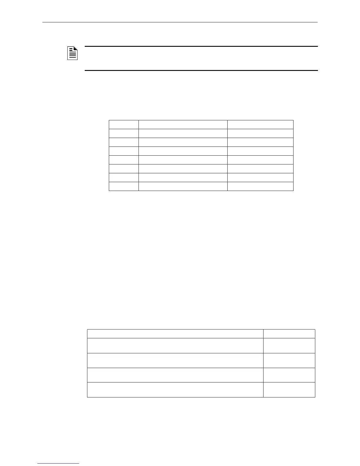
2.6.2 Short Circuit Isolators
The control cards and modules of the Safety Bus system are provided with short circuit isolators on
both communication links. A short circuit on a link is signaled both locally (on the modules) and on
the control panel. The short circuit isolator have the following electric characteristics:
2.6.3 Response Time
The I/O modules must promptly communicate alarms, anomalies and the analog values of the con-
trol boards. The time it takes the input module to communicate an alarm to the panel depends on
various factors, including:
• The number of modules on the communication ring
• The physical position of the module on the communication ring
• Whether or not there is a failure along the communication ring
• The quality of communication along the ring
In any case, in the most unfavorable operating conditions (64-module loop, with a failure along the
communication ring) the system guarantees alarm signaling within one second and therefore con-
siderably less than required by UL standards. The other types of signals having a lower priority
level are received by the panel with the same delay in conditions of no traffic and slightly delayed
in case of other events having a higher priority on the ring. The table below shows some Safety Bus
response times at maximum configuration (64 I/O modules with two control boards):
NOTE: As the system is able to support a single failure along the communication ring, it is
important to diagnose and repair failures as soon as they are signaled by the panel, in order to
guarantee correct system operation without degrading the security level.
Parameter Description Value
IL max Max leak current with open switch 10 mA AC
RF Operating resistance 10 - 10.5 Ω
RF Reset resistance 11.5 - 12 Ω
ISO max Max operating current 7 mA AC
ISO min Min operating current 5.5 mA AC
ISC max Max reset current 5.3 mA AC
ISC min Min reset current 5 mA AC
Figure 2.7 Electric Characteristics of Short Circuit Isolators
Sequence Typical Time
Alarm received by the panel coming from an input module with no failures along the
communication ring
100 milliseconds
Alarm received by the panel coming from an input module with one failure along the
communication ring
200 milliseconds
Output module activation following an alarm coming from an input module with no
failures along the communication ring
200 milliseconds
Output module activation following an alarm coming from an input module with one
failure along the communication ring
400 milliseconds
Figure 2.8 Ring Response Time
 Loading...


