Safety Bus Manual — P/N LS10177-000HI-E:B 02/21/2019 28
SB-AIM Module System Components
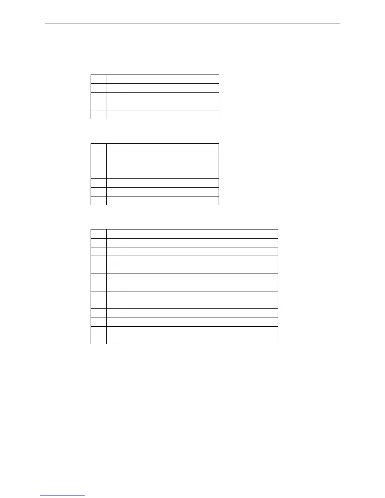
3.4.3 Connections
The SB-AIM features the following connectors:
Terminal Block TB1
This terminal block supplies power to the module.
Terminal Block TB2
This terminal block connects the two ring communication links.
Terminal Block TB3
This terminal block is used to connect analog channels L1, L2, L3, and L4.
Pin Tag Function
1 +V 24VDC Power supply positive
2 +V 24VDC Power supply positive
3 -V 24VDC Power supply negative
4 -V 24VDC Power supply negative
Pin Tag Function
1 -LK1 Link-1 Negative
2 +LK1 Link-1 Positive
3 SLK1 Link-1 Screen
4 -LK2 Link-2 Negative
5 +LK2 Link-2 Positive
6 SLK2 Link-2 Screen
Pin Tag Function
1 +V1 Ch-1 24VDC Power supply positive (250mA max.) to field device
2 -V1 Ch-1 24VDC Power supply negative (250mA max.) to field device
3 +L1 Ch-1 4-20mA input
4 +V2 Ch-2 positive power supply (250mA max.) to field device
5 -V2 Ch-2 negative power supply (8250mA max.) to field device
6 +L2 Ch-2 4-20mA input
7 +V3 Ch-3 positive power supply (250mA max.) to field device
8 -V3 Ch-3 negative power supply (8250mA max.) to field device
9 +L3 Ch-3 4-20mA input
10 +V4 Ch-4 positive power supply (250mA max.) to field device
11 -V4 Ch-4 negative power supply (8250mA max.) to field device
12 +L4 Ch-4 4-20mA input
 Loading...


