17 Safety Bus Manual — P/N LS10177-000HI-E:B 02/21/2019
Introduction Local Power Supplies
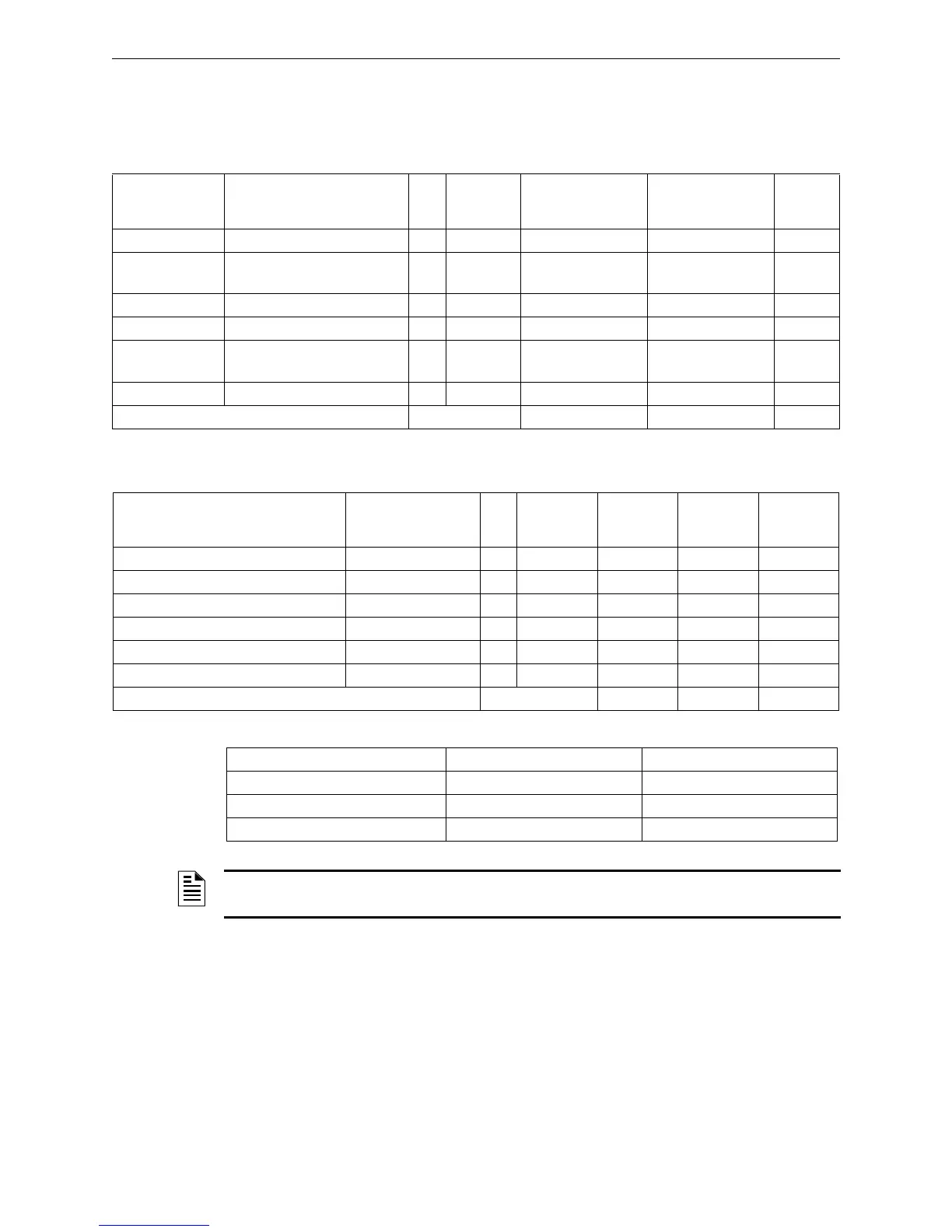
2.8.1 Sizing the Local Power Supply
Use the tables below for sizing the power supply units and batteries.
Module Current Consumption
External Load Current Consumption
Complete System Current Consumption
Part Number Description Qty.
Current in
standby
Total current in
standby
Current in alarm
Total
current
in alarm
SB-SIM
Supervised input modules
115 mA 500 mA
SB-SIM-GM
Supervised input modules with
ground monitor
115 mA 500 mA
SB-AIM
4-20mA analog input module
119 mA 2.5 A
SB-SCM
Solenoid valve output module
98 mA 3.719 A
1
SB-NCM
Notification appliances signal
output module
88 mA 2.5 A
SB-ECM
I/O module
159 mA 3 A
Total current In stand by (A1) In alarm (B1)
1 This value is not to be exceeded.
Part Number Description Qty.
Current in
standby
Total
current in
standby
Current in
alarm
Total
current in
alarm
Notification appliances
Solenoid valves
Gas detectors
Flame detectors
Repetition relay
Other loads
Total current In stand by (A2) In alarm (B2)
Description Total Current in Standby Total Alarm Current
Module current consumption (A1) (B1)
External load current consumption (A2) (B2)
Total Current (A3) (B3)
NOTE: Power supply shall be sized according to the highest current consumption between
stand by and alarm conditions. In most cases the current in alarm condition is the highest.
 Loading...


