19 Safety Bus Manual — P/N LS10177-000HI-E:B 02/21/2019
Section 3: System Components
This section contains the technical specifications and instruction for connecting the components
that make up the Safety Bus.
3.1 S81-F7011-1 Control Board
This board manages communication with the I/O modules. It monitors the communication ring and
receives all the signals coming from the I/O modules. It can be used in either mono or duplex con-
figuration mode, to increase the system availability.
3.1.1 Technical Specifications
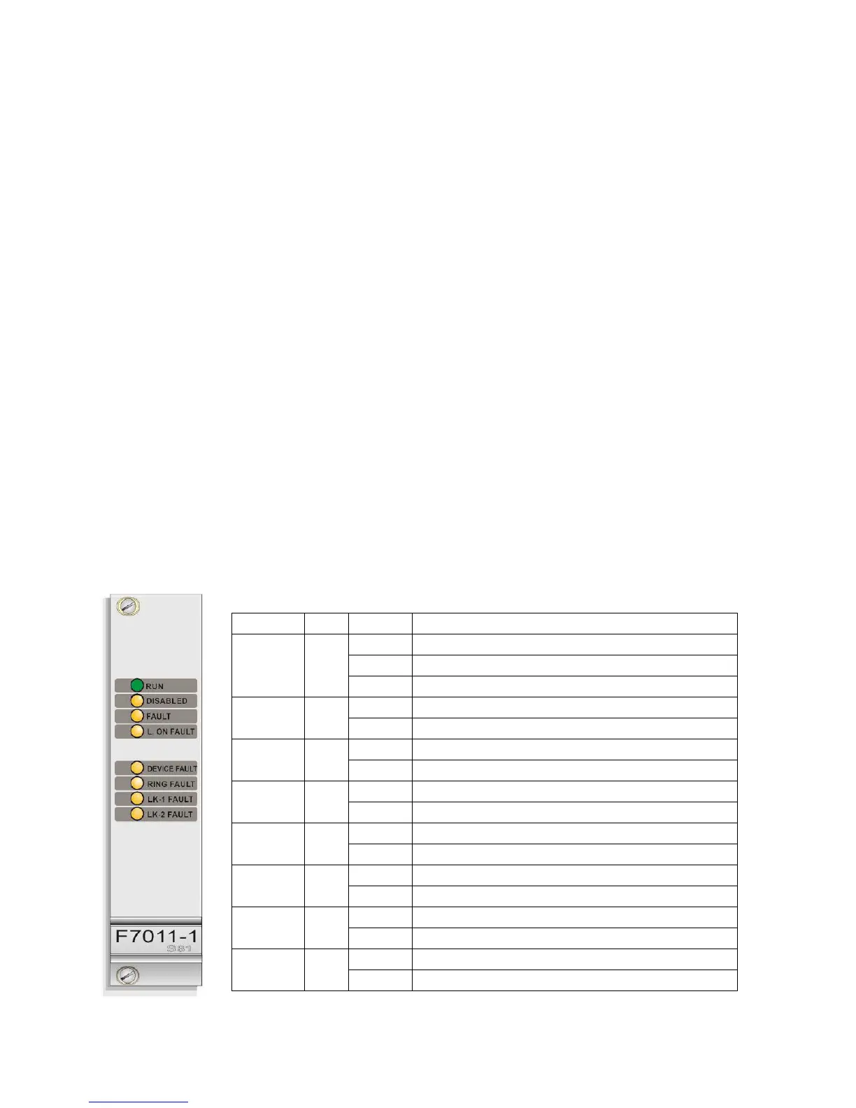
3.1.2 Visual Indicators
The front panel of the board features 8 LEDs that indicate the following conditions:
• Redundancy: Yes
• Max number of modules per ring: 64
• Nominal Power supply voltage: 24 VDC
• Power limited Circuits: Yes
• Supervised Circuits: Open line, Short Circuit, and Ground Fault
• NAC Synchronization: On Card Basis
• Max Current (standby): 110 mA
• Operating temperature: 0 / 49 °C (32 / 120.2° F)
• Storage temperature: -55 / 85°C (-67 / 185°F)
• Max Communication Bit Rate: 1.2 kHz
• Max humidity: 0-95% non condensing
• Max Line Impedance: 20 ft (6.096 m) in same room, in conduit
• Ground Fault Impedance: </ 500 ohms
• Max distance in copper between the panel
and the first/last module:
20 ft (6.096 m) in conduit
Tag Color Mode Condition
Run Green
Off Board out of order
Blinking Board in Slave mode
On Solid Board in Master mode
Disabled Yellow
Off No channel/point disabled
On Solid At least one channel/point disabled
Fault Yellow
Off No line device fault
Blinking Line/device Fault
L. On Fault Yellow
Off No discrepancy between programmed and detected modules
Blinking Discrepancy between programmed and detected modules
Device Fault Yellow
Off No module failure
Blinking Module failure
Ring Fault Yellow
Off No interruption of communication ring
Blinking Communication ring interrupted
LK-1 Fault Yellow
Off Communication on Link LK1 present
Blinking Communication failure on Link LK1
LK-2 Fault Yellow
Off Communication on Link LK2 present
Blinking Communication failure on Link LK2
 Loading...


