133
• Secondary: Indicates that the user logs in from the peer device, and the user data is synchronized
from the peer device to the local device. The local device is in synchronization state. It only receives
and processes the synchronization messages and does not process packets from the server.
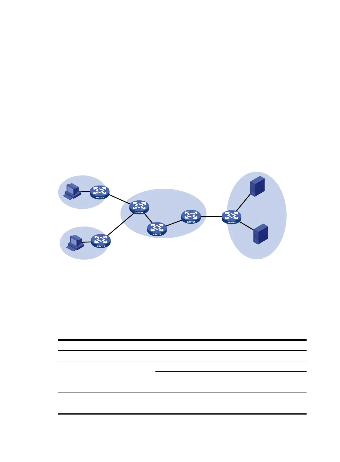
Portal authentication across VPNs
This feature is not applicable to VPNs with overlapping address spaces.
In a scenario where the branches belong to different VPNs that are isolated from each other and all
portal users in the branches need to be authenticated by the server at the headquarters, you can deploy
portal authentication across MPLS VPNs. As shown in Figure 44, the P
E connecting the authentication
clients serves as the NAS. The NAS is configured with portal authentication and AAA authentication,
both of which support authentication across VPNs. The NAS can transmit a client's portal authentication
packets in a VPN transparently through the MPLS backbone to the servers in another VPN. This feature
implements centralized client authentication across different VPNs while ensuring the separation of
packets of the different VPNs.
Figure 44 Network diagram for portal authentication across VPNs
Portal authentication configured on MCE devices can also support authentication across VPNs. For
information about MCE, see Layer 3 - IP Routing Configuration Guide.
For information about AAA implementation across VPNs, see "Configuring AAA."
Portal configuration task list
Complete these tasks to configure Layer 2 portal authentication:
Task Remarks
Specifying the local portal server for Layer 2 portal authentication Required
Configuring the local portal server
Customizing authentication pages Optional
Configuring the local portal server Required
Enabling Layer 2 portal authentication Required
Controlling access of portal
users
Configuring a portal-free rule
Optional
Setting the maximum number of online portal users
P
MPLS backbone
PE
PE
CE
CE
CE
VPN 1
VPN 2
VPN 3
AAA
server
Portal server
Host
Host
NAS

 Loading...


