407
MFF configuration examples
Auto-mode MFF configuration example in a tree network
Network requirements
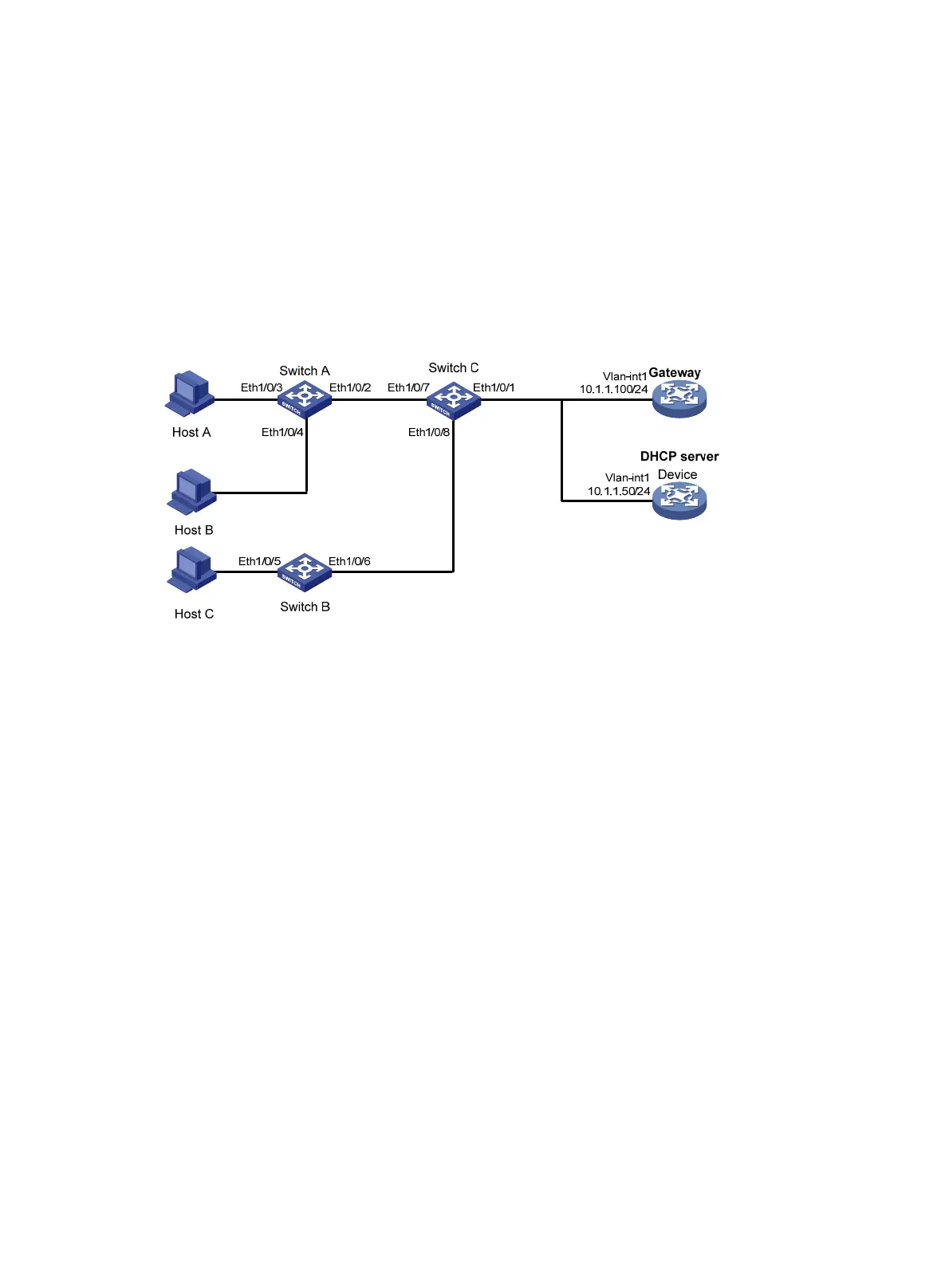
As shown in Figure 130, all the devices are in VLAN 100. Host A, Host B, and Host C obtain IP addresses
from the DHCP server. They are isolated at Layer 2, and can communicate with each other through the
gateway. MFF automatic mode is enabled on Switch A and Switch B.
Figure 130 Network diagram
Configuration procedure
1. Configure the IP address of VLAN-interface 1 on the gateway.
<Gateway> system-view
[Gateway] interface Vlan-interface 1
[Gateway-Vlan-interface1] ip address 10.1.1.100 24
2. Configure the DHCP server:
# Enable DHCP, and configure a DHCP address pool.
<Device> system-view
[Device] dhcp enable
[Device] dhcp server ip-pool 1
[Device-dhcp-pool-1] network 10.1.1.0 mask 255.255.255.0
# Add the gateway's IP address into DHCP address pool 1.
[Device-dhcp-pool-1] gateway-list 10.1.1.100
[Device-dhcp-pool-1] quit
# Configure the IP address of VLAN-interface 1.
[Device] interface Vlan-interface 1
[Device-Vlan-interface1] ip address 10.1.1.50 24
3. Configure Switch A:
# Enable DHCP snooping.
<SwitchA> system-view
[SwitchA] dhcp-snooping
# Enable MFF in automatic mode.

 Loading...


