343
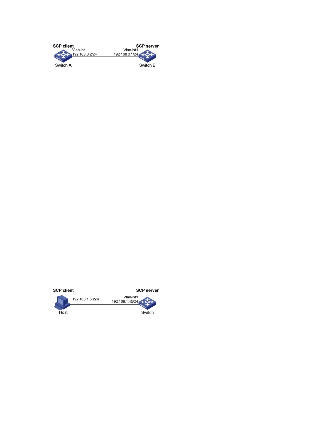
Figure 103 Network diagram
Configuration procedure
# Create VLAN-interface 1 and assign an IP address to it.
<SwitchA> system-view
[SwitchA] interface vlan-interface 1
[SwitchA-Vlan-interface1] ip address 192.168.0.2 255.255.255.0
[SwitchA-Vlan-interface1] quit
# Download the file remote.bin from the SCP server, save it locally and change the file name to local.bin.
<SwitchA> scp 192.168.0.1 get remote.bin local.bin
Username: test
Trying 192.168.0.1 ...
Press CTRL+K to abort
Connected to 192.168.0.1 ...
The Server is not authenticated. Continue? [Y/N]:y
Do you want to save the server public key? [Y/N]:n
Enter password:
18471 bytes transfered in 0.001 seconds.
SCP server configuration example
Unless otherwise noted, devices in the configuration example are operating in non-FIPS mode.
Network requirements
As shown in Figure 104, the switch acts as the SCP server, and the host acts as the SCP client. The host
establishes an SSH connection to the switch. The user uses the username test and the password aabbcc.
The username and password are saved on the switch for local authentication.
Figure 104 Network diagram
Configuration procedure
# Generate RSA key pairs.
<Switch> system-view
[Switch] public-key local create rsa
The range of public key size is (512 ~ 2048).
NOTES: If the key modulus is greater than 512,
It will take a few minutes.
Press CTRL+C to abort.

 Loading...


