408
[SwitchA] vlan 100
[SwitchA-vlan-100] mac-forced-forwarding auto
[SwitchA-vlan-100] quit
# Configure Ethernet 1/0/2 as a network port.
[SwitchA] interface ethernet 1/0/2
[SwitchA-Ethernet1/0/2] mac-forced-forwarding network-port
# Configure Ethernet 1/0/2 as a DHCP snooping trusted port.
[SwitchA-Ethernet1/0/2] dhcp-snooping trust
4. Configure Switch B:
# Enable DHCP snooping.
<SwitchB> system-view
[SwitchB] dhcp-snooping
# Enable MFF in automatic mode.
[SwitchB] vlan 100
[SwitchB-vlan-100] mac-forced-forwarding auto
[SwitchB-vlan-100] quit
# Configure Ethernet 1/0/6 as a network port.
[SwitchB] interface ethernet 1/0/6
[SwitchB-Ethernet1/0/6] mac-forced-forwarding network-port
# Configure Ethernet 1/0/6 as a DHCP snooping trusted port.
[SwitchB-Ethernet1/0/6] dhcp-snooping trust
Auto-mode MFF configuration example in a ring network
Network requirements
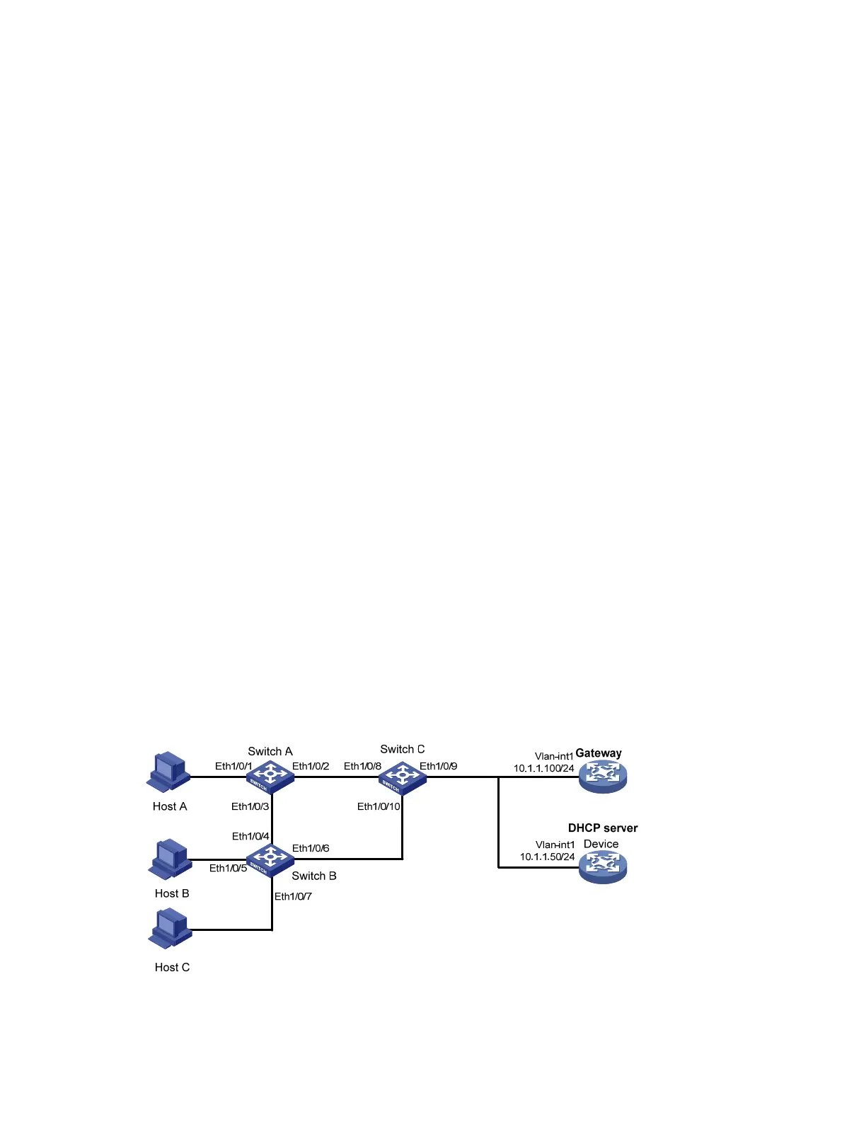
As shown in Figure 131, all the devices are in VLAN 100, and the switches form a ring. Host A, Host B,
and Host C obtain IP addresses from the DHCP server. They are isolated at Layer 2, and can
communicate with each other through the gateway. MFF automatic mode is enabled on Switch A and
Switch B.
Figure 131 Network diagram
Configuration procedure
1. Configure the IP address of VLAN-interface 1 on the gateway.

 Loading...


