370
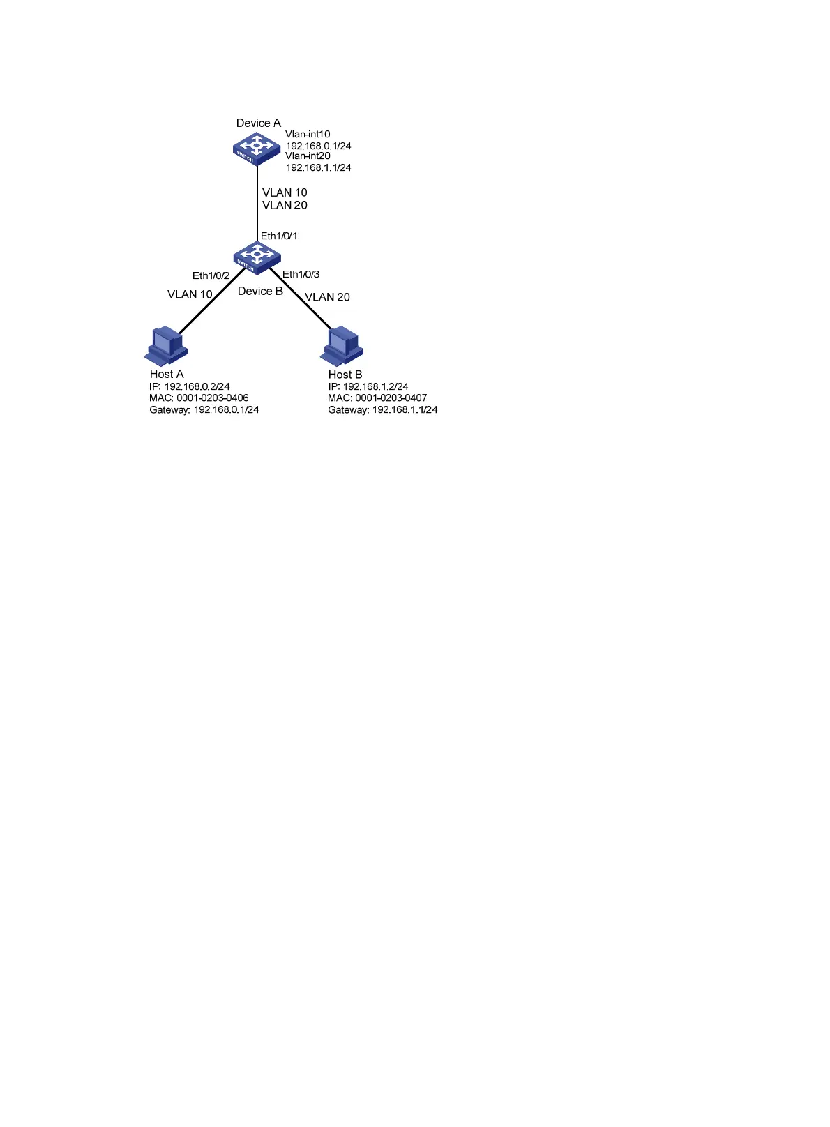
Figure 115 Network diagram
Configuration procedure
# Create VLAN 10, and assign Ethernet 1/0/2 to VLAN 10.
<DeviceB> system-view
[DeviceB] vlan 10
[DeviceB-vlan10] port ethernet1/0/2
[DeviceB-vlan10] quit
# Create VLAN 20, and assign Ethernet 1/0/3 to VLAN 20.
[DeviceB] vlan 20
[DeviceB-vlan20] port ethernet1/0/3
[DeviceB-vlan20] quit
# Configure the link type of Ethernet 1/0/1 as trunk, and permit packets of VLAN 10 and VLAN 20 to
pass the interface.
[DeviceB] interface ethernet1/0/1
[DeviceB-Ethernet1/0/1] port link-type trunk
[DeviceB-Ethernet1/0/1] port trunk permit vlan 10 20
[DeviceB-Ethernet1/0/1] quit
# Configure IPv4 source guard on Ethernet 1/0/2 and Ethernet 1/0/3 to filter packets based on both
the source IP address and MAC address.
[DeviceB] interface ethernet1/0/2
[DeviceB-Ethernet1/0/2] ip verify source ip-address mac-address
[DeviceB-Ethernet1/0/2] quit
[DeviceB] interface ethernet1/0/3
[DeviceB-Ethernet1/0/3] ip verify source ip-address mac-address
[DeviceB-Ethernet1/0/3] quit
# Configure global static IP binding entries to deny attack packets that exploit the IP address or MAC
address of Host A and Host B.
[DeviceB] ip source binding ip-address 192.168.0.2 mac-address 0001-0203-0406
[DeviceB] ip source binding ip-address 192.168.1.2 mac-address 0001-0203-0407

 Loading...


