384
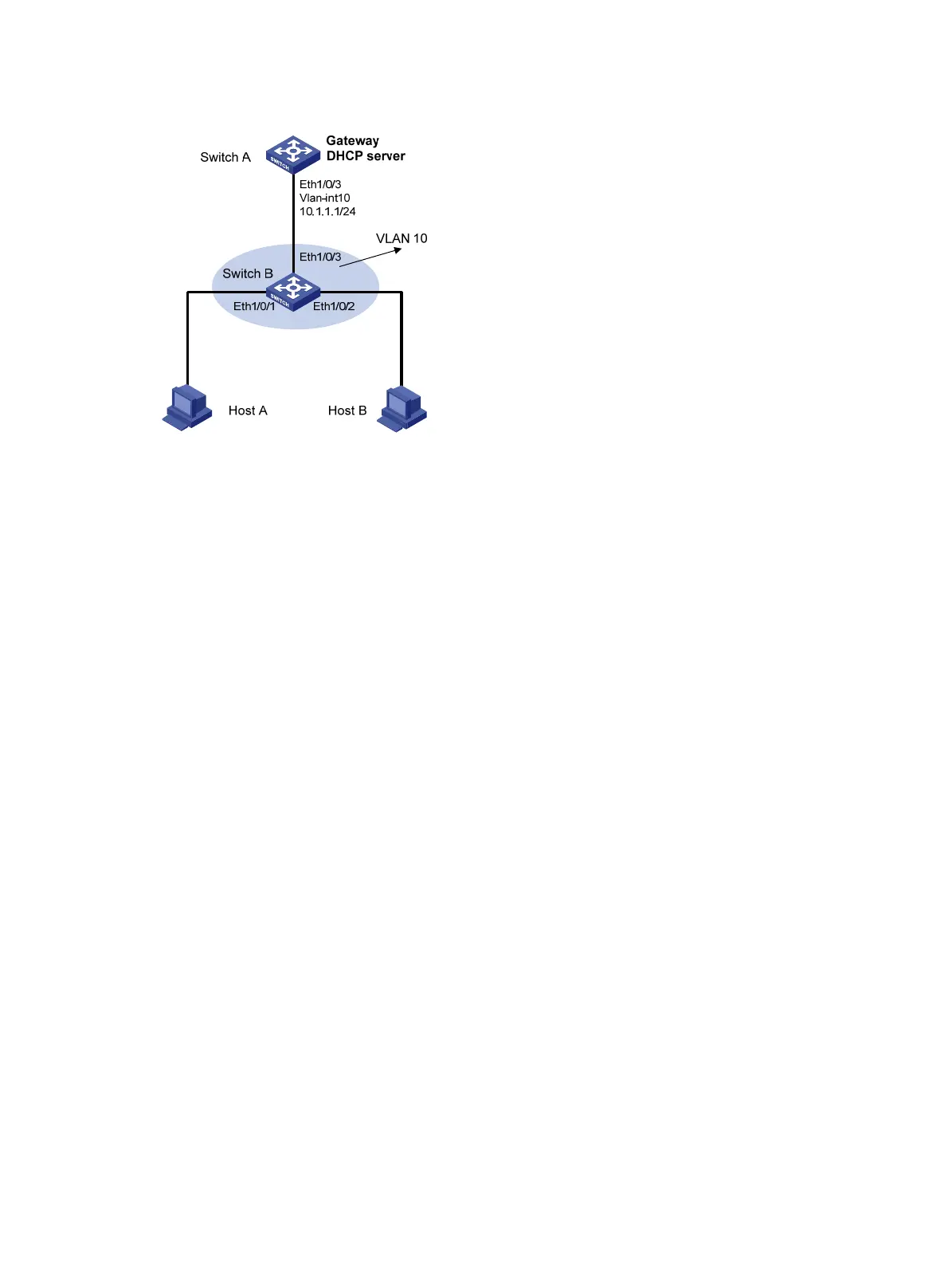
Figure 118 Network diagram
Configuration procedure
1. Add all ports on Switch B into VLAN 10, and configure the IP address of VLAN-interface 10 on
Switch A. (Details not shown.)
2. Configure Switch A as a DHCP server:
# Configure DHCP address pool 0.
<SwitchA> system-view
[SwitchA] dhcp enable
[SwitchA] dhcp server ip-pool 0
[SwitchA-dhcp-pool-0] network 10.1.1.0 mask 255.255.255.0
3. Configure Host A and Host B as 802.1X clients and configure them to upload IP addresses for ARP
detection. (Details not shown.)
4. Configure Switch B:
# Enable the 802.1X function.
<SwitchB> system-view
[SwitchB] dot1x
[SwitchB] interface ethernet 1/0/1
[SwitchB-Ethernet1/0/1] dot1x
[SwitchB-Ethernet1/0/1] quit
[SwitchB] interface ethernet 1/0/2
[SwitchB-Ethernet1/0/2] dot1x
[SwitchB-Ethernet1/0/2] quit
# Add local access user test.
[SwitchB] local-user test
[SwitchB-luser-test] service-type lan-access
[SwitchB-luser-test] password simple test
[SwitchB-luser-test] quit
# Enable ARP detection for VLAN 10.
[SwitchB] vlan 10
[SwitchB-vlan10] arp detection enable

 Loading...


