FINAL TRIM SIZE : 7.0 in x 8.5 in
B
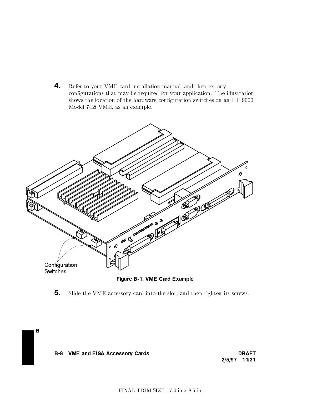
4.
Refer to your VME card installation man
ual, and then set an
y
congurations that may be required for y
our application. The illustration
shows the lo cation of the hardw
are conguration switches on an HP 9000
Mo del 742i VME, as an example.
Figure B-1. VME Card Example
5.
Slide the VME accessory card into the slot, and then tighten its screws.
B-8 VME and EISA Accessory Cards DRAFT
2/5/97 11:31

 Loading...