FINAL TRIM SIZE : 7.0 in x 8.5 in
B
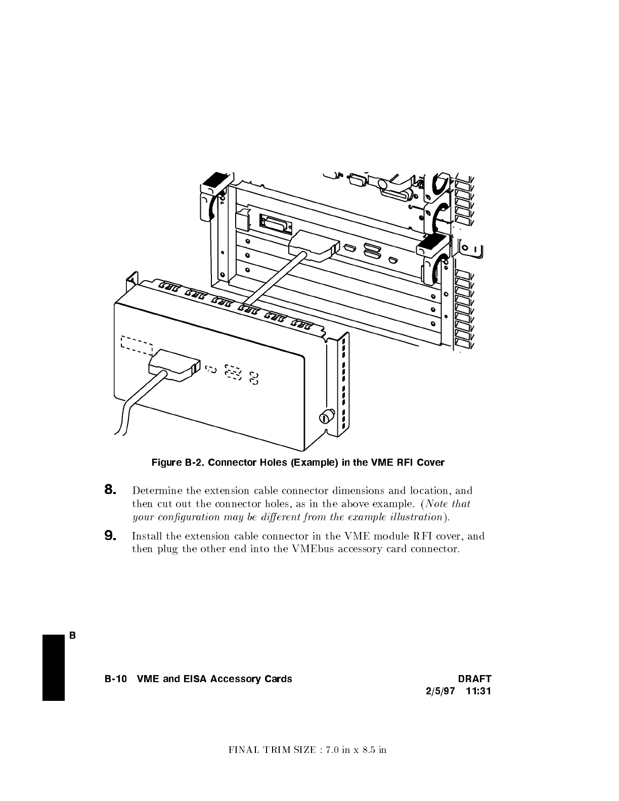
Figure B-2. Connector Holes (Example) in the VME RFI Co
ver
8.
Determine the extension cable connector dimensions and lo cation, and
then cut out the connector holes, as in the ab o
ve example. (
Note that
your conguration may be dierent from the example il lustration
).
9.
Install the extension cable connector in the VME mo dule RFI co
ver, and
then plug the other end into the VMEbus accessory card connector.
B-10 VME and EISA Accessory Cards DRAFT
2/5/97 11:31

 Loading...