139
Chapter 6: Solving Problems
Solving Emulation Probe Problems
On a good system, the RESET LED will light and the BKG and USER
LEDs will be out.
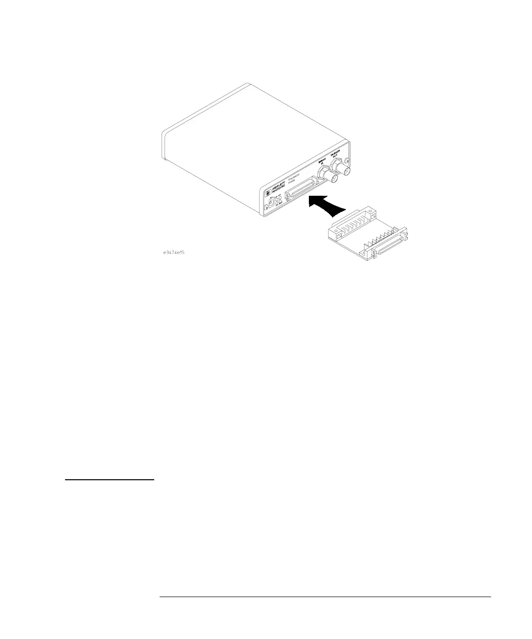
2 Connect a coaxial cable between BREAK IN and TRIGGER OUT.
3 Set all of the switches to CLOSED.
This is standard RS-232 at 9600 baud which can be connected directly
to a 9 pin RS-232 interface that conforms to the IBM PC-AT 9 pin
standard.
4 Use a terminal emulator to connect to the emulation probe.
5 Enter the pv 1 command.
See Also Options available for the “pv” command are explained in the help
screen displayed by typing “help pv” or “? pv” at the prompt.
([DPSOHV Here are some examples of ways to use the pv command.
To execute both tests one time:
pv 1
To execute test 2 with maximum debug output repeatedly until a Ctrl-c
is entered:
pv -t2 -v9 0