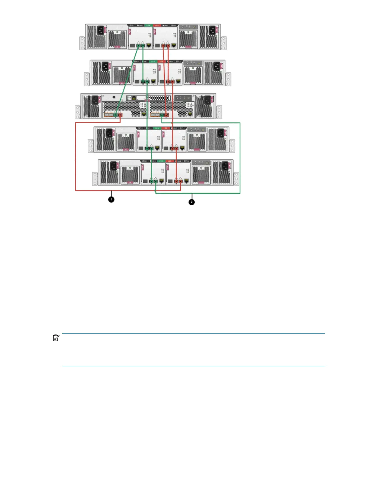
1. This cable connects controller 1, device port 1B (top left - Cntrl 1, DP1B) to I/O module B, port 2
(bottom right - I/O B, P2).
2. This cable connects controller 2, device port 1A (top right - Cntrl 2, DP1A) to I/O module A, port 2
(bottom left - I/O A, P2).
Figure 23 Fibre Channel cabling for the EVA (rear view, mid-mounted controller)
Connecting Fibre Channel cables to the EVA4400 (front end)
You can cable the front end of your EVA4400 either to external Fibre Channel switches or directly
to servers. See Figure 24 and Figure 26 for front end connections with server-based management.
See Figure 25 and Figure 27 for front end connections with array-based management.
NOTE:
The cabling diagrams in Figure 24 through Figure 27 require fabric connect mode, which is the
default as shipped.
HP StorageWorks 4400 Enterprise Virtual Array installation guide 83
 Loading...