NOTE:
Additional external switches can be connected to the HSV300-S controller enclosure.
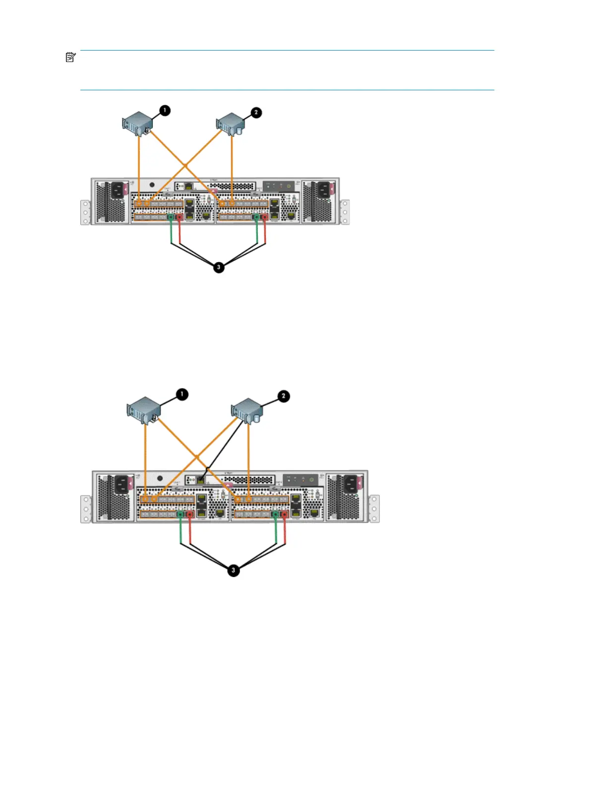
1. Management server
2. Database server
3. Indicates cabling connections to disk enclosures. See Figure 22 and Figure 23 for cabling connections.
Figure 28 HSV300-S controller enclosure in a direct connect configuration with server-based
management
1. File server
2. Database server
3. Indicates cabling connections to disk enclosures. See Figure 22 and Figure 23 for cabling connections.
Figure 29 HSV300-S controller enclosure in a direct connect configuration with array-based management
EVA4400 cabling diagrams86
 Loading...