13
Maintenance point
An MP is configured on a port and belongs to an MA. MPs include the following types: maintenance
association end points (MEPs) and maintenance association intermediate points (MIPs).
• MEP
MEPs define the boundary of the MA. Each MEP is identified by a MEP ID.
The MA to which a MEP belongs defines the VLAN of packets sent by the MEP. The level of a
MEP equals the level of the MD to which the MEP belongs. The level of packets sent by a MEP
equals the level of the MEP.
The level of a MEP determines the levels of packets that the MEP can process. A MEP forwards
packets at a higher level and processes packet of its level or lower. The processing procedure
is specific to packets in the same VLAN. Packets of different VLANs are independent.
MEPs include inward-facing MEPs and outward-facing MEPs:
{ An outward-facing MEP sends packets to its host port.
{ An inward-facing MEP does not send packets to its host port. Rather, it sends packets to
other ports on the device.
• MIP
A MIP is internal to an MA. It cannot send CFD packets actively; however, it can handle and
respond to CFD packets. By cooperating with MEPs, a MIP can perform a function similar to
ping and traceroute. A MIP forwards packets of a different level without any processing and only
processes packet of its level.
The MA to which a MIP belongs defines the VLAN of packets that the MIP can receive. The
level of a MIP is defined by its generation rule and the MD to which the MIP belongs. MIPs are
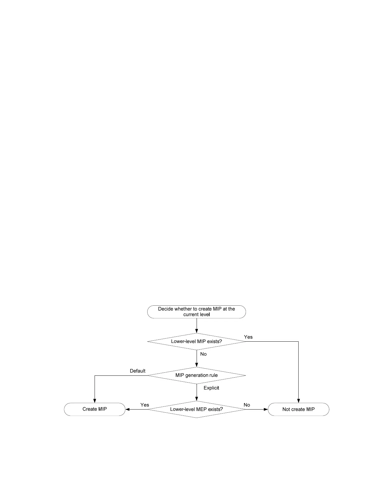
generated on each port automatically according to the following MIP generation rules:
{ Default rule—If no lower-level MIP exists on an interface, a MIP is created on the current
level. A MIP can be created even if no MEP is configured on the interface.
{ Explicit rule—If no lower-level MIP exists and a lower-level MEP exists on an interface, a
MIP is created on the current level. A MIP can be created only when a lower-level MEP is
created on the interface.
If a port has no MIP, the system will check the MAs in each MD (from low to high levels), and
follow the procedure as described in Figure 3 to cre
ate or not to create MIPs at the current level.
Figure 3 Procedure of creating MIPs
Figure 4 demonstrates a grading example of the CFD module. Four levels of MDs (0, 2, 3, and 5) are
designed. The bigger the number, the higher the level and the larger the area covered. MPs are
configured on the ports of Device A through Device F. Port 1 of Device B is configured with the

 Loading...