9
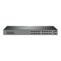
Figure 6 Mounting bracket installation positions and grounding positions on an HPE
5710-54HT switch
(1) Mounting bracket installation position near the power supply side
(2) Primary grounding point (3) Auxiliary grounding point
(4) Mounting bracket installation position near the port side
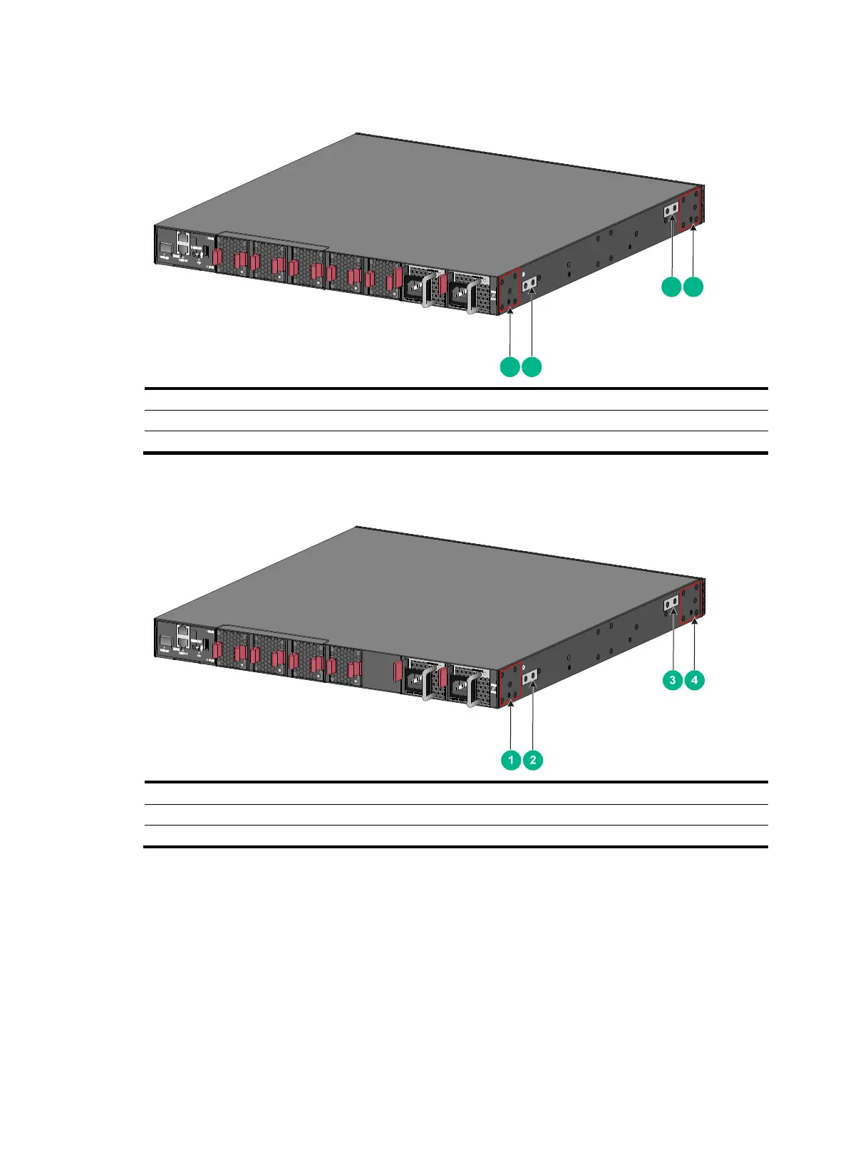
Figure 7 Mounting bracket installation positions and grounding positions on an HPE
5710-30HT switch
(1) Mounting bracket installation position near the power supply side
(2) Primary grounding point (3) Auxiliary grounding point
(4) Mounting bracket installation position near the port side
Attaching the mounting brackets and chassis rails to the chassis
The mounting bracket and chassis rail installation methods are the same for the HPE 5710-54HF
and HPE 5710-30HF switches.
To attach the mounting brackets and chassis rails to the chassis:
1. Align the mounting brackets with the screw holes in the chassis. Use M4 screws (provided) to
attach the mounting brackets to the chassis.
{ To install the mounting brackets at the port side, see Figure 8, Figure 9, and Figure 10.
{ To install the mounting brackets at the power supply side, see Figure 11, Figure 12,
and Figure 13.
21
43

 Loading...