System maintenance switch
Position Default Function
S1 O
O = iLO security is enabled.
On = iLO security is disabled.
S2 O
O = System configuration can be changed.
On = System configuration is locked.
S3 O Reserved
S4 O Reserved
S5 O
O = Power-on password is enabled.
On = Power-on password is disabled.
S6 O
O = No function.
On = ROM reads system configuration as invalid.
S7 O Reserved
S8 — Reserved
S9 O Reserved
S10 — Reserved
S11 — Reserved
S12 — Reserved
CAUTION: Clearing CMOS, NVRAM, or both deletes configuration information. Be sure to configure the server blade
properly to prevent data loss.
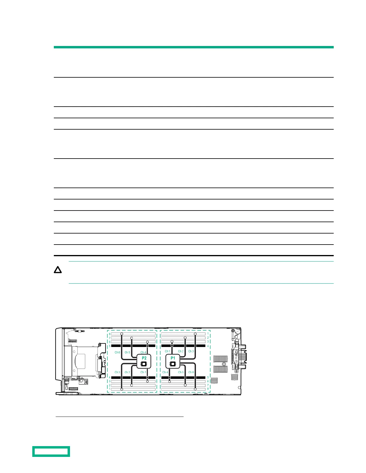
DIMM slot locations
DIMM slots are numbered sequentially (1 through 8) for each processor and designate the DIMM slot ID for population
rules and spare replacement.
For specific DIMM population information, see the DIMM population guidelines on the Hewlett Packard Enterprise website
(http://www.hpe.com/docs/memory-population-rules).
Component identification
98
 Loading...