14. Connect all necessary internal cabling to the expansion board.
For more information on these cabling requirements, see the documentation that ships with the option.
15. Install the server board assembly.
16.
Install the chassis cover.
17. Connect all necessary external cabling to the expansion board.
For more information on these cabling requirements, see the documentation that ships with the option.
18. If removed, install the security padlock and/or the Kensington security lock.
For more information, see the lock documentation.
19.
Connect all peripheral cables to the server.
20.
Connect the power adapter to the server, and then secure the power adapter cord in the power cord clip.
21.
Connect the power cord to the AC source.
22.
Power up the server.
The installation is complete.
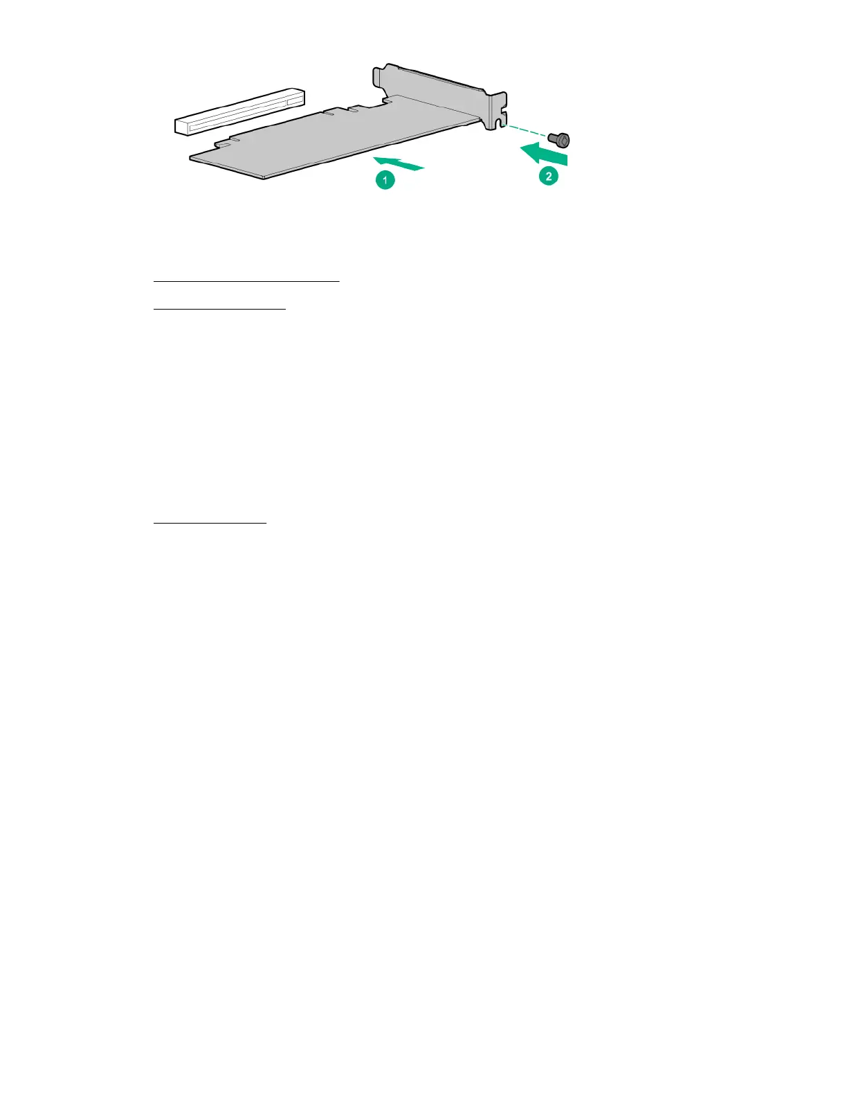
Remove the air bale from the expansion board
Procedure
Remove the air
bale from the expansion board.
The number and location of the latches that secure the bale to the board will vary depending on the expansion board.
The illustration below is an example image only. See the expansion board documentation for model-specific information.
50
Hardware options installation