Shenzhen Hpmont Technology Co., Ltd Chapter 9 Options
HD30 Series Inverters User Manual ―131―
Chapter 9 Options
9.1 Extension I/O Card (HD30-EIO)
HD30 series inverters using with extension I/O card (HD30-EIO) can achieve the extension of
analogue input, digital input and relay contact output, shown as Figure 9-1.
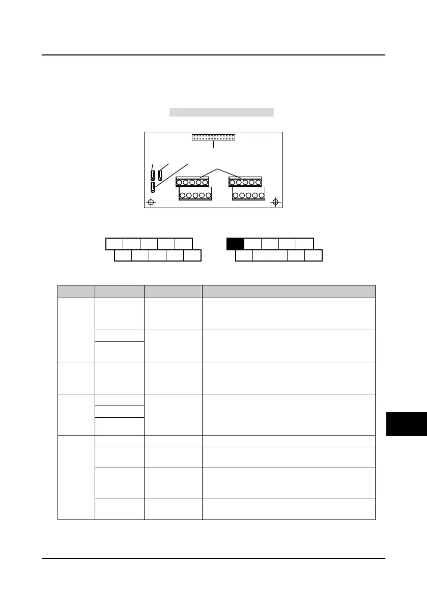
Figure 9-1 Extension I/O card
9.1.1 Terminal Description of Extension I/O Card
Figure 9-2 Extension I/O card terminal layout
Table 9-1 Extension I/O card terminal function description
Analogue
input
AI3 Analogue input
Input voltage/current are selectable
Input voltage range: -10V-10V (input impedance 32kΩ);
Input current range: 0-20mA (input impedance 500Ω)
AI4+
Analogue
differential input
Input voltage/current are selectable
Input voltage range: -10V-10V (input impedance 34kΩ);
Input current range: 0-20mA (input impedance 500Ω)
AI4-
Digital input
DI7-DI9 Digital input 7-9
Programmable bipolar optional input signal
Input voltage range: 0-30VDC
Input impedance: 4.7kΩ
Relay
output
R2A/R2B/R2C
Relay contact
output
Programmable output, contact rating: 250VAC/3A or
30VDC/1A
RB、RC: Normally closed;
RA、RC: Normally open
R3A/R3B/R3C
R4A/R4B/R4C
Power
supply
GND Analogue ground Analogue ground, isolated to COM
P24 +24V power
Digital input use the +24V, maximum allowable output
current is 200mA
SEL
Digital input
common terminal
Defaulted the SEL and the P24 are short connected.
When using the external power to drive the DI7-DI9, it
need disconnect the SEL and the P24
COM
Digital reference
ground
Digital ground
To connect the control board
Jumper
CN3
Jumper
CN2
Jumper
CN4
HD30-EIO
I/O card terminal
AI3 AI4+ DI7 DI8 DI9 R2A R3A R4AR3B
GND
P24 SEL
COM R2C R4C
AI4- R2B R3C R4B
9

 Loading...


