Shenzhen Hpmont Technology Co., Ltd Chapter 4 Electrical Installation
HD30 Series Inverters User Manual ―23―
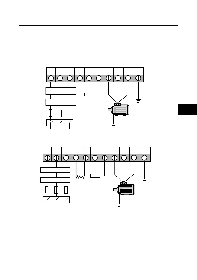
4.3.2 Power Terminal Wiring
During trial operation, make sure the inverter runs forward when the forward command is enabled.
If not, switch any two of the output terminals (U, V, W) or modify the setting of parameter F00.17
to change the motor’s direction.
The power terminal wirings are shown as Figure 4-5, Figure 4-6, Figure 4-7 and Figure 4-8.
The braking resistor and its selection are referred to section 9.5 Braking Unit and Braking
Resistor Selection (page 135).
Figure 4-5 Main circuit connection of 5.5KW or below model
Figure 4-6 Main circuit connection of 7.5-55KW model
L1 L2 L3 (+) (-) BR U V W PE
Optional EMI filter
Optional AC reactor
Fuses
Braking resistor
Mains supply
Supply ground
L1 L2 L3 (+) (-) BR U V W PEP1
Optional EMI filter
Optional AC reactor
Mains supply
Braking resistor
Fuses
DC reactor
(optional)
Supply ground
4

 Loading...


