Shenzhen Hpmont Technology Co., Ltd Chapter 6 Function Introduction
HD30 Series Inverters User Manual ―89―
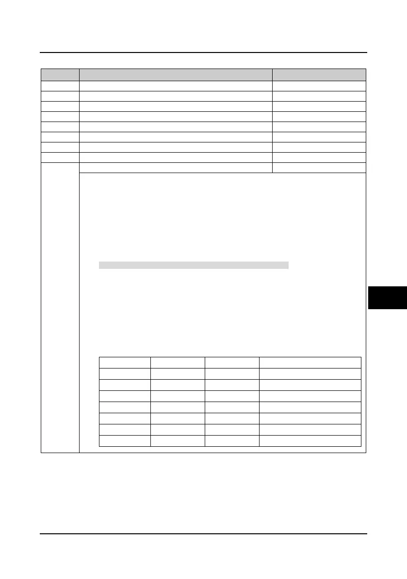
6.2.16 Group F15 Digital I/O Terminal Parameters
No. Name Description Range
factory setting
F15.00 DI1 terminal function selection 0
86
2
DI2 terminal function selection
F15.02 DI3 terminal function selection 0
86
0
DI4 terminal function selection
F15.04 DI5 terminal function selection 0
86
0
DI6 terminal function selection
F15.06 DI7 terminal (option terminal) function selection 0
86
0
DI8 terminal (option terminal) function selection
F15.08 DI9 terminal (option terminal) function selection 0
86
0
0: Reserved. It disables the terminal’s function. The inverter ignores the signal input via this terminal.
• The unwanted terminal is recommended to be set as 0 so as to avoid wrong connection or
action.
1: Inverter enabled.
• When enabled, the inverter is enabled to run;
• When disabled, the inverter is disabled to run and will be in auto stop status.
• If no terminal selects this function, it defaults that the inverter is enabled.
2,3: FWD/REV function. You can set any multi-function terminal for the FWD/REV terminal to control
the inverter’s run and stop.
• When F00.11 = 1 (external terminal reference run command source) or terminal No. 11
function is enabled, FWD/REV function is valid.
• Refer to parameter F15.16.
4: Three-wire operation mode.
• Refer to parameter 15.16.
5,6,7: Frequency source selection 1, 2, 3.
• Up to 2
n
frequency reference sources can be switched through terminal logic combination
setting n (the maximum n is 3). Refer to the below table.
• Up to 8 frequency reference sources can be switched through selecting 3 terminals.
• Up to 4 frequency reference sources can be switched through selecting 2 terminals.
Terminal 3 Terminal 2 Terminal 1 Selection
0 0 0 Holding
0 0 1 Display panel digital setting
0 1 0 Terminal digital setting
0 1 1 SCI communication digital setting
1 0 0 Analogue value setting
1 0 1 Terminal pulse setting
1 1 X Hold
6

 Loading...


