Chapter 4 Electrical Installation Shenzhen Hpmont Technology Co., Ltd
―36― HD30 Series Inverters User Manual
4.5.3 Wiring Motor
Longer the cable between the inverter and the motor is, higher the high-frequency leakage
current is, causing the inverter output current to increase as well. This may affect peripheral
devices.
When the cable between the motor and the inverter is longer than 100 meters, it is recommended
to install output reactor and adjust the carrier frequency as per the instruction in Table 4-5.
Table 4-5 Carrier frequency and the cable length between inverter and motor
Cable length < 30m 30-50m 50-100m ≥ 100m
Carrier frequency
15kHz below 10kHz below 5kHz below 2kHz below
The inverter should be derated if the motor cables are too long or their cross sectional area (CSA)
is too large. The inverter’s cables should be the cables with specified CSA (see Table 4-1)
because the capacitance of the cable to ground is in proportional to the cable’s CSA. If the cable
with big CSA is used, its current should be reduced. The current should be decreased by 5%
when per level of CSA is increased.
4.5.4 Ground Connections
The earth terminals PE must be connected to earth properly. The earthing cable should be as
short as possible (the earthing point should be as close to the inverter as possible) and the
earthing area should be as large as possible.
The grounding resistance should be less than 10Ω for 380V Class inverters.
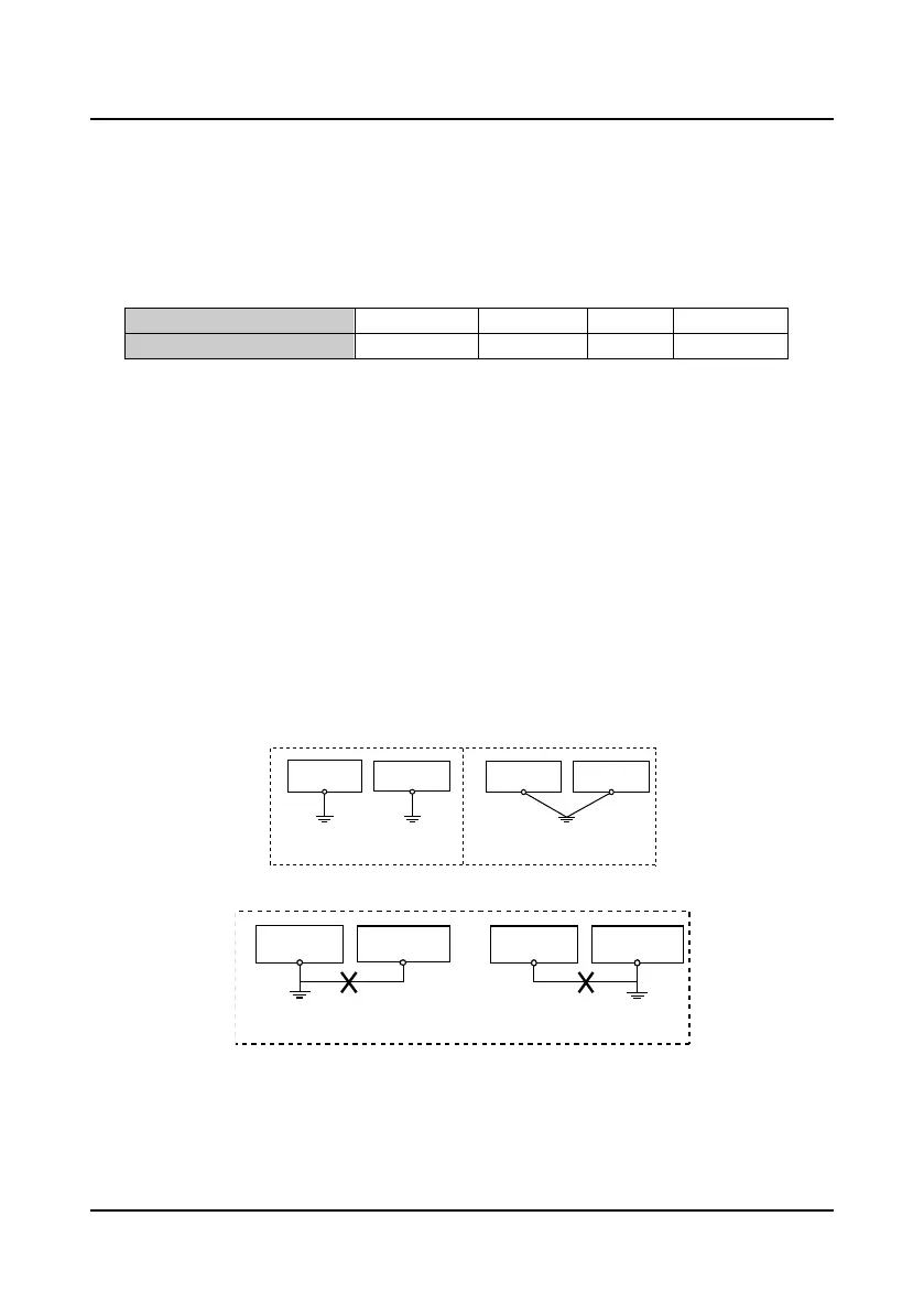
Do not share the earth wire with other devices such as welding machines or power tools. It could
share the earthing pole, but the motor and the inverter each have their own earthing pole, then
the earthing effect is better. The recommended and avoided earthing methods are respectively
shown in Figure 4-26 and Figure 4-27.
Figure 4-26 Recommended earthing method
Figure 4-27 Avoided earthing method
HD30
Dedicated earthingpole
(optimal)
PE
PE
Sharingearthingpole
(good)
HD30Otherdevices Otherdevices
PE
PE
HD30 HD30Other devices
Other devices
Sharing earthing pole
(not so good)

 Loading...


