Shenzhen Hpmont Technology Co., Ltd Chapter 4 Electrical Installation
HD30 Series Inverters User Manual ―19―
Chapter 4 Electrical Installation
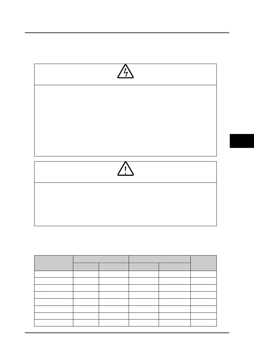
4.1 Wiring Precautions
• Only qualified electrical engineer can perform wiring job.
• Only when the power supply switch is completely off can you do the wiring job.
• You can’t open the inverter cover to do wiring operation until the power is cut-off 10 minutes later.
Do not wire or detach the inverter internal devices at power-on situation.
• Do not do wiring operation until the internal charge indicator of the inverter is off and the voltage
between (+) and (-) of the main circuit terminals is below 36V.
• Check the wiring carefully before connecting emergency stop or safety circuit.
• The earth terminal PE of the inverters must be reliable earthing. It must use two separate earth wire
due to the leakage current from the inverter to ground.
• It must use Type B mode when utilize earth leakage protection devices(ELCB/RCD).
• Do not touch the wire terminals of the inverter when it is live. The main circuit terminals is neither
allowed connecting to the enclosure nor short-circuiting.
• Do not do dielectric strength test on the inverter.
• Do wiring connection of the braking resistor or the braking unit according to the wiring figure.
• Make sure the terminals are fixed tightly.
• Do not connect the AC supply cable to the output terminals U, V, W of the inverter.
• Do not connect the phase-shifting capacitors to the output circuit.
• Be sure the inverter has ceased output before switching motor or change-over switches.
• The inverter DC bus terminals must not be short-circuited.
4.2 Selection of Main Circuit Peripheral Devices
Please refer to the Table 4-1 for the recommended specifications.
Table 4-1 HD30 series inverters I/O wiring specification
Model
Input Protection Main Circuit (mm
2
)
Control
Circuit (mm
2
)
MCCB (A) Contactor (A) Supply Cables Motor Cables
HD30-2D0P4G 16 10 1.0 1.0 ≥0.5
HD30-2D0P7G 16 10 1.5 1.5 ≥0.5
HD30-2D1P5G 20 16 2.5 1.5 ≥0.5
HD30-2D2P2G 32 20 4.0 2.5 ≥0.5
HD30-2T3P7G 40 32 4.0 4.0 ≥0.5
HD30-2T5P5G 63 40 6.0 6.0 ≥0.5
HD30-2T7P5G 63 40 6.0 6.0 ≥0.5
HD30-2T011G 100 63 16 16 ≥0.5
4

 Loading...


