Shenzhen Hpmont Technology Co., Ltd Chapter 4 Electrical Installation
HD30 Series Inverters User Manual ―21―
4.3 Main Circuit Terminals and Wiring
• The bare portions of the power cables must be bound with insulation tapes.
• Ensure that AC supply voltage is the same as inverter’s rated input voltage.
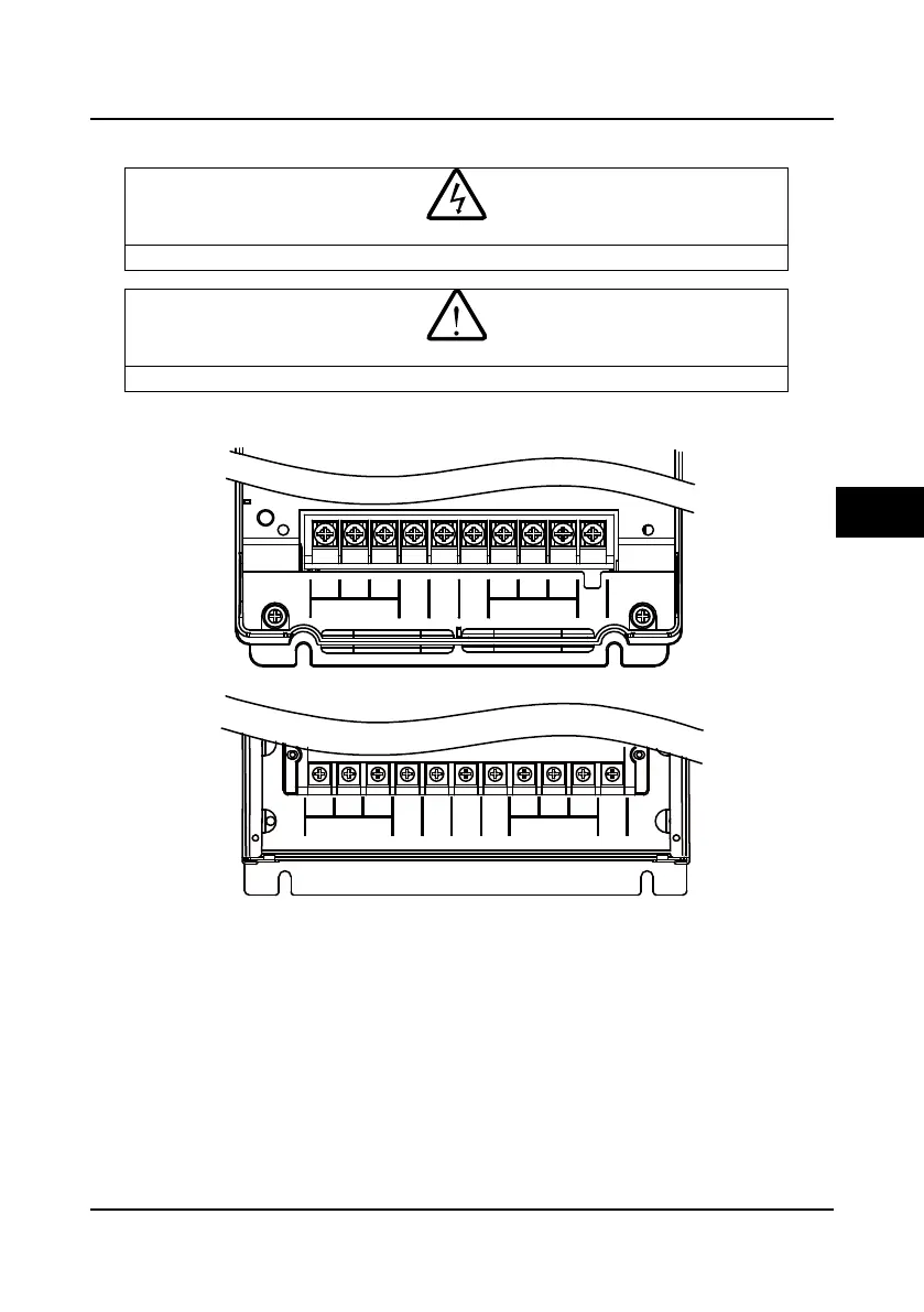
4.3.1 Power Terminal Description
Figure 4-1 Main circuit terminal layout of 5.5kW or below model
Figure 4-2 Main circuit terminal layout of 7.5-55kW model
POWER
BR
(+) (-)
MOTOR
PE
L3
L1 L2
W
U V
POWER
BR
(+) (-)
MOTOR
PE
L3
L1 L2
W
U V
P1
4

 Loading...


