Shenzhen Hpmont Technology Co., Ltd Chapter 4 Electrical Installation
HD30 Series Inverters User Manual ―25―
4.4 Control Terminals and Wire Connection
• The control circuit is designed as ELV (Extra Low Voltage) circuit and basically isolated with the
power circuit. Do not touch the control circuit when the inverter is on power.
• If the control circuit is connected to the external devices with live touchable port (SELV circuit), it
should increase an additional isolating barrier to ensure that SELV classification of external devices
not be changed.
• If connect the communication terminal of the control circuit to the PC, you should choose the
RS485/232 isolating converter which meets the safety requirement.
In order to efficiently suppress the interference to control signals, the length of signal cables
should be less than 50m and keep a distance of at least 0.3m from the power lines. Please use
twisted-pair shielded cables for analogue input and output signals.
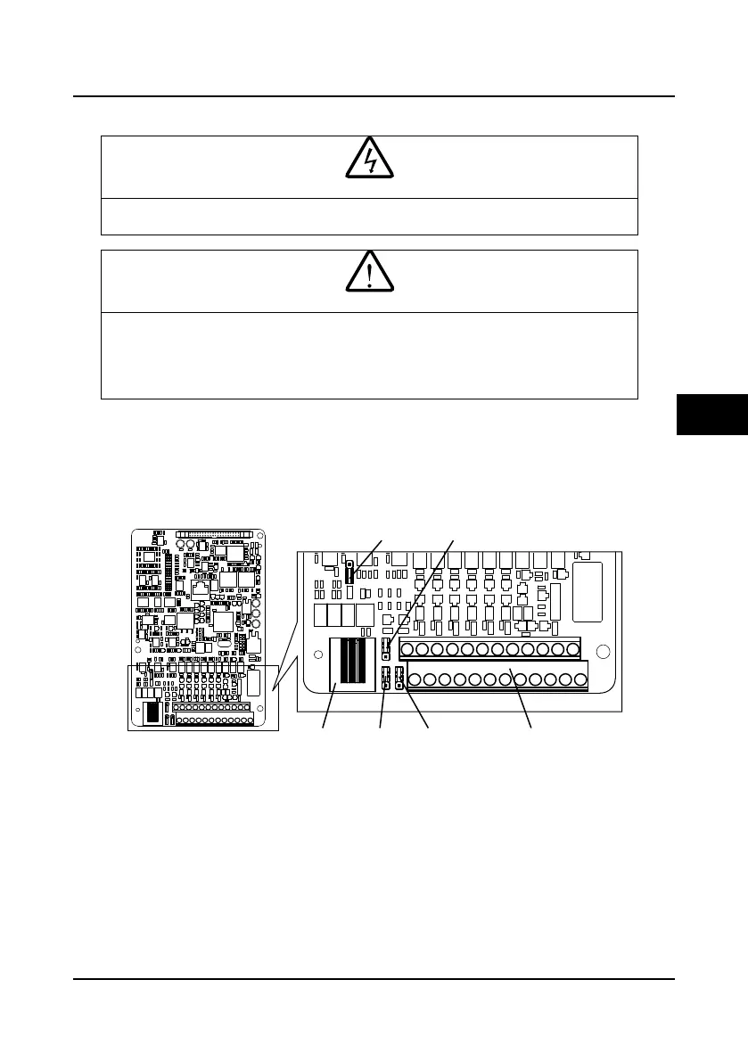
The positions of control terminal, wire jumper and SCI communication port in the control PCB are
shown in Figure 4-9.
Figure 4-9 Positions of control terminal, wire jumper and SCI communication port in the control PCB
SCI
communicationport
Controlterminal
Wire jumper
CN9
Wire jumper
CN6
Wire jumper
CN7
Wire jumper
CN8
4

 Loading...


