Chapter 4 Electrical Installation Shenzhen Hpmont Technology Co., Ltd
―28― HD30 Series Inverters User Manual
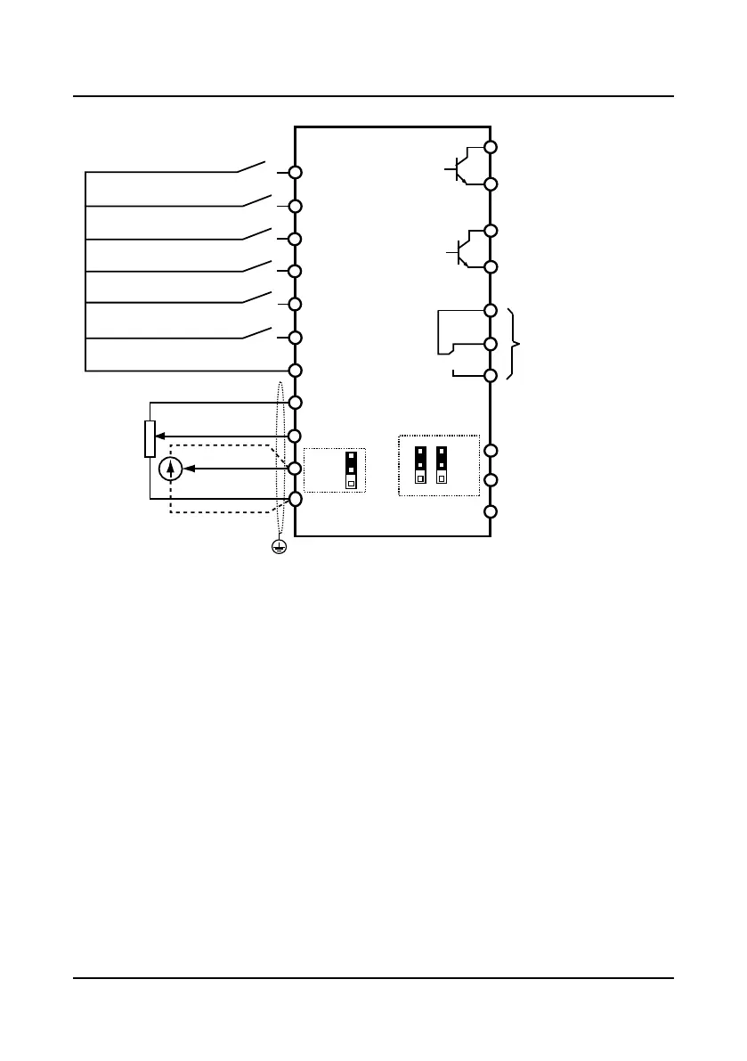
4.4.4 Control Terminal Connection
Figure 4-12 HD30 control circuit connection diagram
DI1
DO2
DO1
CME
R1A
R1C
R1B
DO1 reference ground
GND
AO1
AO2
DI2
DI3
DI4
DI5
DI6
COM
AI1
AI2
+10
HD30
GND
COM
DO2 reference ground
Multi-function input terminal 1
Multi-function input terminal 2
Multi-function input terminal 3
Multi-function input terminal 4
Multi-function input terminal 6
Multi-function input terminal 5
Digital ground
Analogue input 1
Analogue input 2
Analogue ground
Analogue ground
Analogue output channel 2
Analogue output channel 1
Programmable
relay output
Programmable open-collector
output channel 1
Programmable open-collector
output channel 2
control board
PE
Shielded cable
CN7
1
3
CN8
1
3
CN9
1
3

 Loading...


