Shenzhen Hpmont Technology Co., Ltd. Chapter 6 Function Introduction
HD3N Series User Manual V1.1 - 79 -
Ref. code Function Description Setting Range [Default]
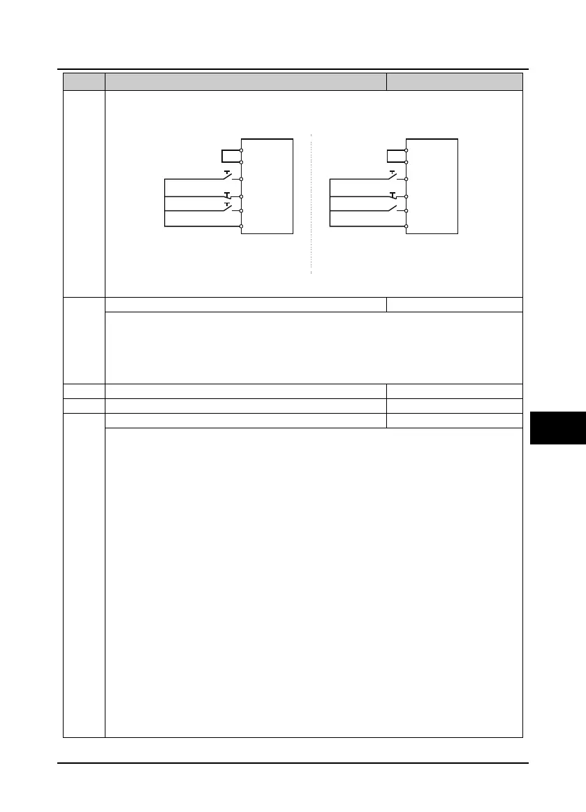
3: Three-wire running mode 2.
• If SB2 changes from enabled into disabled, HD3N will keep the same mode.
• Three-wire running mode: DI terminal is defined as No. 4 function.
Action selection when extrenal device has fault
Protection action when external device has fault.
0: Coast to stop.
1: Emergency stop.
2: Decelerate to stop.
3: Continue to run.
F15.19 DO2 function 0 - 38 [0]
0: Unused.
1: Inverter is ready.
• HD3N completes power on and no fault occurs, then it can normally run.
2: Inverter running. HD3N is in run status.
3: Forward running. HD3N is forward running.
4: Reverse running. HD3N1 is reverse running.
5: DC brake. HD3N is DC brake.
6: Zero-frequency status.
• In zero-frequency range, the output frequency (including in stop status) outputs.
• Refer to F15.28 and F15.29.
7: Zero-frequency running.
• HD3N output frequency is within zero-frequency range.
• Refer to F15.28 and F15.29.
9,10: Frequency level detection signal (FDT1,FDT2).
• Refer to F15.31 - F15.35.
11: Frequency within FAR range (FAR).
• The output frequency is within FAR range.
• Detection range is set by F15.27.
12: Frequency upper limit.
• Indicating signal will output when setting frequency ≥ upper limit frequency.
13: Frequency lower limit.
• Indicating signal will output when setting frequency ≤ lower limit frequency.
COM
F15.16=2 F15.16=3
P24
SEL
DIx
DIz
DIy
COM
P24
SEL
DIx
DIz
DIy
SB2 SB2
SB3
K
SB1 SB1
FWD
FWD /REV
RUN
REV
SB1: Normally closedstop button
SB2: Normally openforward button
SB3: Normally open reverse button
K: Directionselectionterminal (level on)
K = 0(forward) K = 1(reverse)
SB1: Normally closed stopbutton
SB2: Normally open run button
Three-wire Three-wire

 Loading...

