Installation Manual – Antenna & Feeder System Installation
BTS3802C & RRU
Chapter 2
Installing RF Antenna & Feeder System
2-38
1
2
3
4
5
6
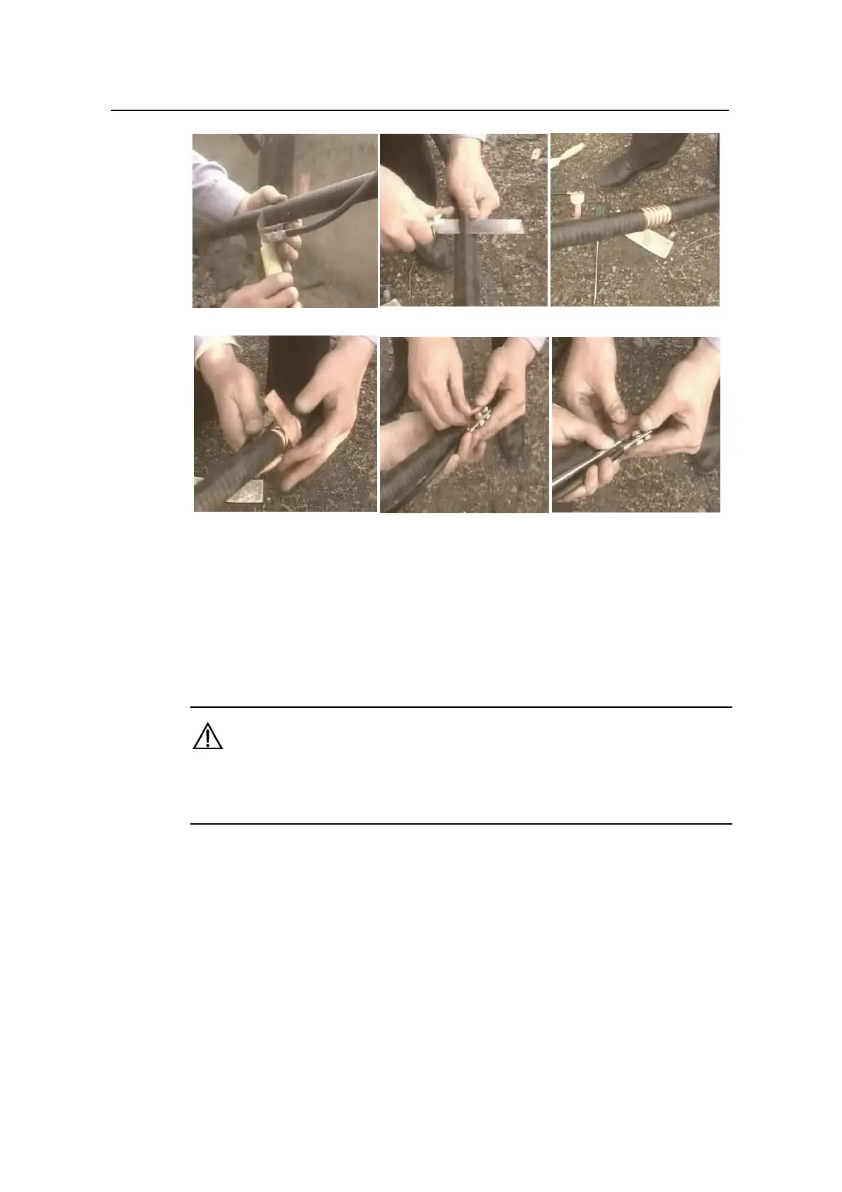
Figure 2-36
Installation of the feeder grounding clips
3) Wrap the copper sheet of the feeder grounding clip around the conductor of the
feeder tight and screw the fixing bar using the straight screwdriver to force
against the grounding cable of the feeder, as shown in 4, 5 and 6 of Figure 2-36.
Caution
The grounding cable of the clip shall be led downward and the angle resulting from the grounding cable
and the feeder shall be no larger than 15
0
. Make sure the feeder grounding clip bends properly.
4) Implement waterproof and encapsulation treatment to the grounding point. See
"2.18.1 Waterproof Treatment for Outdoor Connectors".
5) Connect the grounding cable of the grounding clip to the grounding part of the
cabling rack securely.