NOTE
Two BBUs are configured in a triple-mode base station. The new BBU is installed in the extension APM30H
cabinet, and it does not have monitoring functions. For details about monitoring principles, see Monitoring
Principles for the Cabinets.
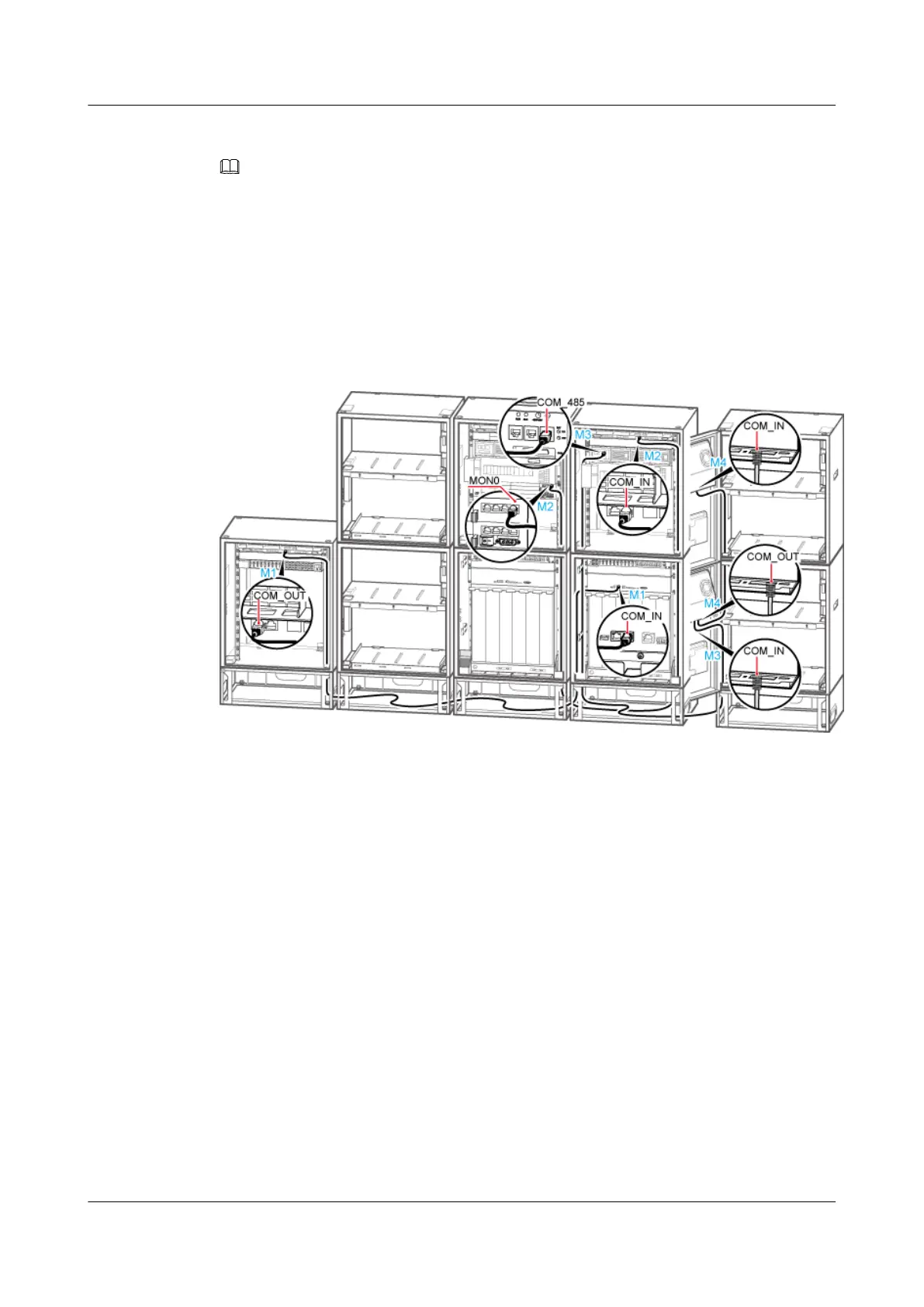
1. Install the monitoring signal cable between the cascaded CMUAs between the TMC11H
and the extension RFC. Connect one end of the cable to the COM_OUT port on the CMUA
in the fan box of the TMC11H and the other end to the COM_IN port on the CMUA in the
fan box of the extension RFC, as shown in Figure 12-51.
Figure 12-51 Installing the monitoring signal cable in the scenario of 2 RFCs+2 APM30Hs+4
IBBS200Ds/IBBS200Ts+1 TMC11H
2. Install the monitoring signal cable between the CMUA and the BBU between the APM30H
and the extension APM30H. Connect one end of the cable to the MON0 port on the UEIU
in the BBU in the APM30H and the other end to the COM_IN port on the CMUA on the
cabinet door of the extension APM30H, as shown in Figure 12-51.
3. Install the monitoring signal cable for the batteries between the extension APM30H and
the extension IBBS200D/IBBS200T. Connect one end of the cable to the COM_485 port
on the PMU in the extension APM30H and the other end to the COM_IN port on the CMUA
on the cabinet door of the lower extension IBBS200D/IBBS200T, as shown in Figure
12-51.
4. Install the monitoring signal cable between the cascaded CMUAs between the extension
IBBS200D/IBBS200T and the extension IBBS200D/IBBS200T. Connect one end of the
cable to the COM_IN port on the CMUA on the cabinet door of the upper extension
IBBS200D/IBBS200T and the other end to the COM_OUT port on the CMUA on the
cabinet door of the lower extension IBBS200D/IBBS200T, as shown in Figure 12-51.
5. Attach labels to the installed cables. For details, see Attaching an L-Shaped Label.
6. Run each cable that leave the cabinet in a PVC corrugated pipe, and then tie the pipe to the
cable hole in the cabinet.
----End
BTS3900A(Ver.B)
Installation Guide 12 Installing the Cables
Issue 01 (2011-10-25) Huawei Proprietary and Confidential
Copyright © Huawei Technologies Co., Ltd.
133