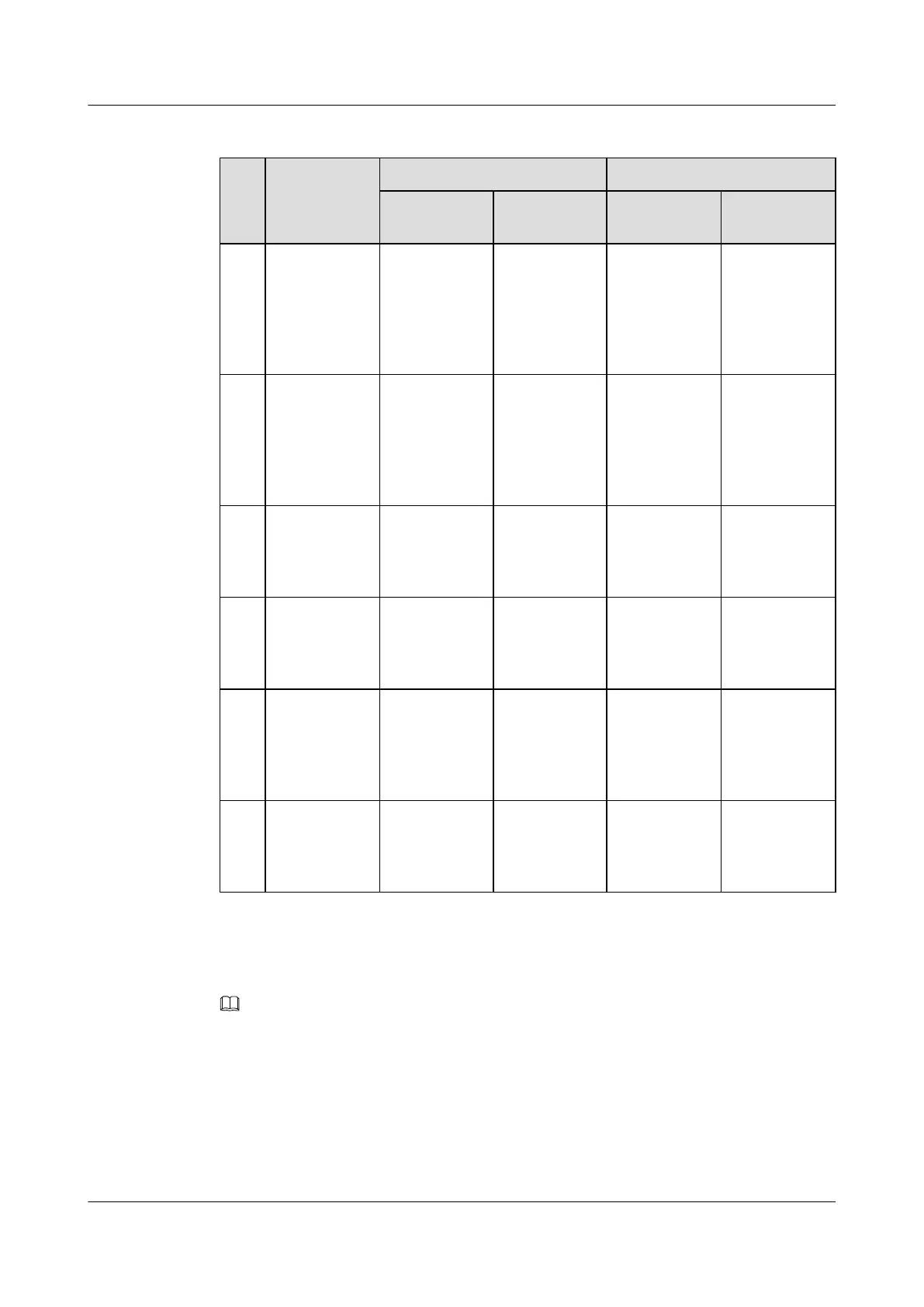
Table 7-5 Signal cables installed in the BTS3900A (-48 V DC) cabinet
No. Cable One End The Other End
Connector Installation
Position
Connector Installation
Position
S1 Monitoring
signal cable
between the
BBU and the
CMUA in the
APM30H
RJ-45
connector
CMUA/
COM_IN
RJ-45
connector
BBU/UPEU/
MON1
S2 Monitoring
signal cable
between the
BBU and the
CMUA in the
RFC
RJ-45
connector
CMUA/
COM_IN
RJ-45
connector
BBU/UPEU/
MON0
S3 Temperature
monitoring
signal cable for
the RFC
4-pin
connector
Fan box in the
RFC/CMUA/
TEM
Temperature
sensor
Air inlet at the
bottom of the
RFC
S4 Signal cable
for the ELU
RJ-45
connector
ELU RJ-45
connector
Fan box in the
APM30H or in
the RFC/
CMUA/ELU
S5 Monitoring
signal cable for
the door status
sensor in the
APM30H
2-pin
connector
Fan box in the
APM30H/
HPMI/GATE
Bare wire Door status
sensor in the
APM30H
S6 Monitoring
signal cable for
the door status
sensor
Cord end
terminal
Fan box in the
RFC/CMUA/
GATE
Bare wire Door status
sensor in the
RFC
Check whether the transmission cables are correctly and securely installed in the cabinet by
referring to Table 7-6.
NOTE
For the transmission cable routing in various RATs and transmission modes, see section Transmission
Cable Connections in the BTS3900A (Ver.B) Hardware Description.
BTS3900A(Ver.B)
Installation Guide 7 Checking the Installed Cables and Modules
Issue 01 (2011-10-25) Huawei Proprietary and Confidential
Copyright © Huawei Technologies Co., Ltd.
35