Procedure
Step 1 Determine the positions for connecting the inter-BBU signal cables according to the actual
interconnection scenarios.
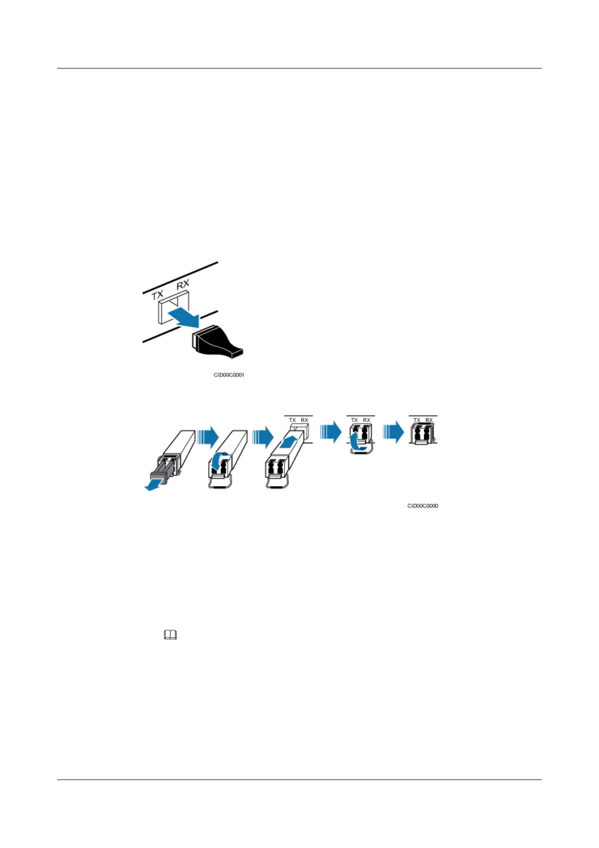
Step 2 Install the optical modules in BBU 0, as shown in Figure 11-32 and Figure 11-33.
1. Remove the dustproof caps from the corresponding ports on BBU 0.
2. Lower the puller on the optical module.
3. Insert the optical modules into the ports.
4. Raise the puller on the optical module.
Figure 11-32 Removing the dustproof cap from the port
Figure 11-33 Installing the optical module
Step 3 Install the inter-BBU signal cable, as shown in Figure 11-34 and Figure 11-35.
1. Remove the dustproof caps from the optical connectors at the end labeled 2A and 2B on
the fiber optic cables, and insert the optical connectors into the optical modules in BBU 0.
2. Route one end of the inter-BBU signal cable into BBU1 in the extension cabinet through
the cable outlet on the right top of the basic cabinet and then the cable outlet on the top of
the extension cabinet.
3. On BBU 1, install optical modules of the same type as those on BBU 0.
NOTE
Optical modules with the same labels are of the same type.
4. Remove the dustproof caps from the optical connectors at the end labeled 1A and 1B on
the fiber optic cables, and insert the optical connectors into the optical modules in BBU 1.
BTS3900L (Ver.C)
Installation Guide
11 Installing the Cables
Issue 07 (2013-11-08) Huawei Proprietary and Confidential
Copyright © Huawei Technologies Co., Ltd.
92