l 3 large-power modules + 3 small-power modules + 1 or 2 BBUs, and RFUs in upper and
lower shelves.
l 3 large-power modules + 1 or 2 BBUs, and RFUs in uppoer or lower shelf.
NOTE
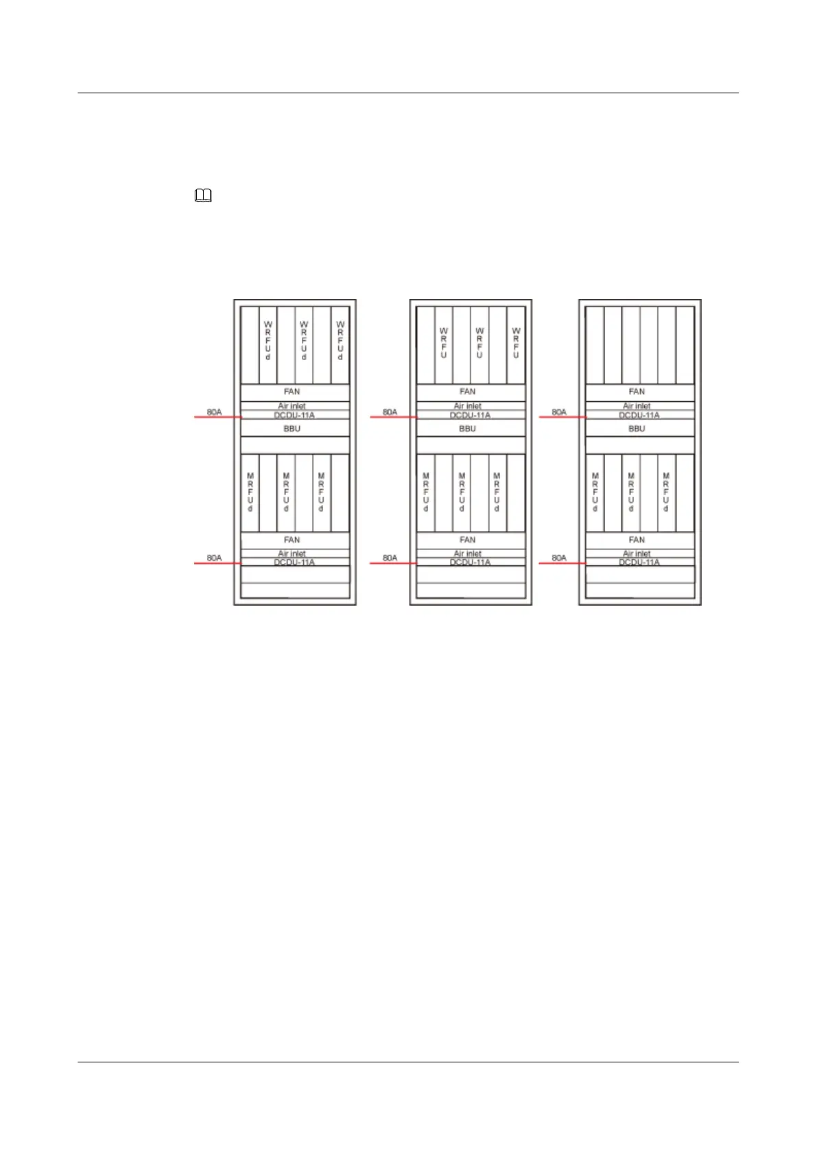
Two 80A air switches, one of them for upper or lower DCDU.
Figure 11-13 shows the small configuration scenarios.
Figure 11-13 Small Configuration Scenario I
Procedure
Step 1 Measure the distance between the DCDU-11A and the external power supply equipment
according to the actual cable route, and then prepare power cables of a proper length.
Step 2 Add an M6 OT terminal to one end of the power cables. For details, see Assembling the OT
Terminal and the Power Cable.
Step 3 Remove the protective cover from the terminal block of the DCDU-11A.
Step 4 Connect the blue cable to the wiring terminal labeled NEG(-) and black cable to the wiring
terminal labeled RTN(+).
Step 5 Use a screwdriver to tighten the screws on the wiring terminals.
Step 6 Install the protective cover, and then use a screwdriver to tighten the screws.
Figure 11-14 shows the installation process.
BTS3900L (Ver.C)
Installation Guide
11 Installing the Cables
Issue 07 (2013-11-08) Huawei Proprietary and Confidential
Copyright © Huawei Technologies Co., Ltd.
75