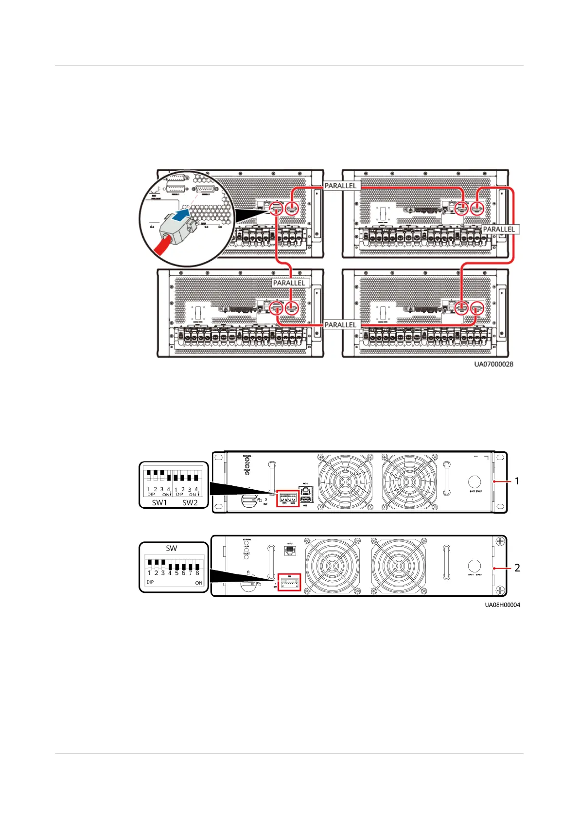
Step 3 Install parallel cables between parallel cabinets.
Figure 6-2 Control cable connection diagram (using four parallel 30 kVA/40 kVA
UPSs as an example)
Step 4 Set the DIP switch for each UPS.
Set the bypass unit DIP switches SW1-DIP4 and SW2-DIP1–SW2-DIP4 or SW-DIP4–
SW-DIP8 to ON to set up parallel communication between MDUs.
Figure 6-3 Setting the DIP switch for each UPS
(1) Bypass unit 1 (BOM number: 02313XPD) or
bypass unit 3 (BOM number: 02313XPE)
(2) Bypass unit 2 (BOM number: 02310SEN) or
bypass unit 4 (BOM number: 02310UCJ)
Step 5 Power on the parallel system.
1. Turn o the external output power switch for each UPS to ensure that the
UPS outputs are independent of each other.
2. Turn on the general bypass and mains input switches.
If the input power is normal, the rectier starts automatically. The MDU starts and
displays the progress bar. Wait until the MDU starts properly.
UPS5000-A-(30 kVA-120 kVA)
User Manual 6 Parallel System Commissioning
Issue 17 (2024-02-21) Copyright © Huawei Digital Power Technologies Co., Ltd. 133
 Loading...