Introduction
Chapter 1 OPERATION MANUAL
V1.3.0en/06.07.15//14.06 Liability for errors and misprints excluded. CC®
The workings of the overtemperature and low-level protection depend the type of temperature
control unit.
1.4.2.1 Temperature control unit (without heater) with classic float switch
Probably the most frequently found type today is the level monitor with a mechanical float switch.
In the bath vessel, a floating body, which is guided in a device, floats on the surface of the thermal
fluid. Depending on the level of the thermal fluid, the float device signals the electronics a state of
good (in case of sufficient filling) or a state of bad (in case of insufficient filling). You should check
the functionality of the float device from time to time. To do so and when in stand-by mode, press
the float body into the bath with a tool (e.g. a screwdriver). The electronics must report an alarm.
1.4.2.2 Temperature control units (with heater) with electronic low level sensor
Combined electronic low level and overtemperature protection
Some temperature control units (device dependent) feature an electronic overtemperature and low-
level protection. Instead of a mechanical float device, temperature sensors are employed on the
surface of the heating coils. These sensors monitor overtemperature at this potential ignition
source, thus ensuring that the controller regulates the heating coil temperatures regulates below
the critical temperature (combustion point of the thermal fluid). This does not apply to Chillers
where the level is capacitively determined). An appropriate message is output via the
>Touchscreen< [88] (see figure »“Pilot ONE”« on page 6).
There is no longer a need for mechanical tools to set the trigger values of the overtemperature
protection. It is replaced by a software engineering tool. The threshold value for the overtempera-
ture protection can be set only if a code, randomly generated by “Pilot ONE”, is entered correctly. As
with the mechanical tool, accidental settings are thus prevented.
1.4.3 Further protective devices
Emergency strategy – isolate the power supply!
Disconnect the temperature control unit from the power supply!
1.4.3.1 Power interruption
Following a power outage (or when switching on the temperature control unit), this function can be
used to determine how the temperature control unit is supposed to respond. This response can be
determined via “Pilot ONE”.
OFF/Standby (Default setting)
After turning the temperature control unit on, thermoregulation is started only after manual input.
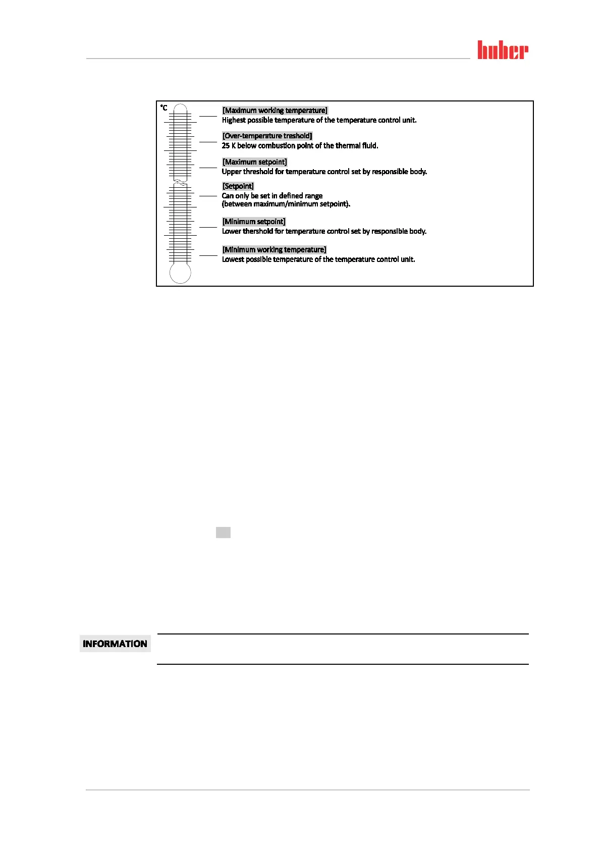
Overview of the tem-
perature thresholds