Function description
Chapter 3 OPERATION MANUAL
V1.3.0en/06.07.15//14.06 Liability for errors and misprints excluded. CC®
▪ The thermal fluid used by you must be chosen in such a way that it not only allows the minimum
and maximum working temperature but is also suitable as regards the combustion point, boiling
point and viscosity. In addition, the thermal fluid must be compatible with all the materials in your
system.
▪ Avoid bending the temperature control and cooling water hoses (if required). Use suitable angle
pieces and lay the hose connections with a large radius. Take the minimum bending radius from
the data sheet of the temperature control hoses used.
▪ The selected hose connections must be resistant to the thermal fluid, the working temperatures
and the permitted maximum pressure.
▪ Check the hoses at regular intervals for any material fatigue (e.g. cracks, leaks).
▪ Keep the length of temperature control hoses as short as possible.
- Always adjust the inside diameter of temperature control hoses to the pump connections.
- Die Viskosität des Thermofluids bestimmt den Druckabfall und beeinflusst das Temperier-
ergebnis besonders bei tiefen Arbeitstemperaturen.
- Too small connectors and couplers and valves can generate significant flow resistance.
Your application will therefore be slower to reach its design temperature.
▪ Only valid for CC®-520w, CC®-525w, CC®-906w and cooling baths used in continuous operation:
Water as well as water and anti-freeze mixes must not be used as thermal fluids!
▪ Basically, you should only use the thermal fluids recommended by the manufacturer and only
within the usable temperature and pressure range.
▪ With temperature control close to the boiling temperature of the thermal fluid, the application
should be roughly at the same height or below the temperature control unit.
▪ Fill the temperature control unit slowly, carefully and evenly. Wear the necessary personal pro-
tective equipment, such as goggles, heat-proof and chemicals-resistant gloves, etc.
▪ After filling and setting all the requisite parameters, the temperature control circuit must be
vented. This is required to ensure trouble-free operation of the temperature control unit and
hence your application.
For water-cooled temperature control units, please take the cooling water temperature necessary
for perfect operation and the required differential pressure from the data sheet from page 83
onward in the Section »Annex«.
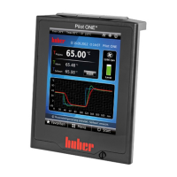
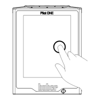
3.4 “Pilot ONE®” controller
Figure »“Pilot ONE”« is shown on page 6.
The basic version of the “Pilot ONE” (Basic) can be upgraded in two stages (from Basic to Exklusiv
and from Exklusiv to Professional or from Exklusiv to Professional with DV-E-grade).
3.4.1 Functional overview of “Pilot ONE®”
You can verify, and optionally upgrade, the delivery version of your temperature control unit using
Pilot ONE, category “E-grade”.
Temperature control units E-grade Basic
E-grade
Exclusive
E-grade
Professional
Brewing thermostats
Unistat temperature control units
UniCAL
Other temperature control units
= Standard equipment,
= Optional,
= Not possible
Overview of the
E-grade variants