Machine Maintenance: 4-8
VACUUM SYSTEM MAINTENANCE
The vacuum pump in this machine is commonly referred to as a “rotary positive
displacement blower” or “blower” for short. The performance and life of the truckmount is
greatly dependent on the care and proper maintenance it receives. Review the blower’s
owner’s manual, which has been included, for a better understanding of this piece of
machinery.
To protect the blower from overloading and damaging itself, a vacuum relief system is
installed on the recovery tank. When the recovery tank inlet is completely sealed o, a
maximum of 12” Hg will be attained.
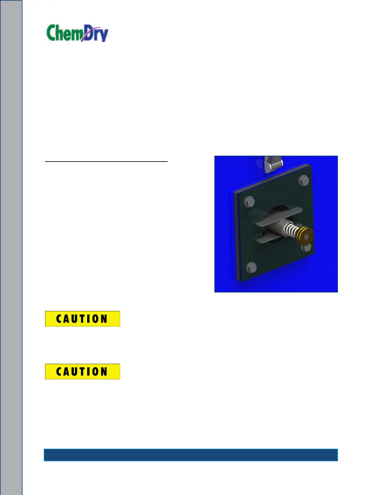
Adjusting the Vacuum Relief Valve
1. Turn the two brass knurled nuts opposite
directions so the inside nut turns freely.
(Two brass knurled nuts are located on the
side of the recovery tank - see Figure 4-2.)
2. Increase the vacuum of the system by
turning the nut clockwise (tightening).
3. Decrease the vacuum of the system
by turning the nut counter-clockwise
(loosening).
4. Once the tank is set to the proper level, turn
the two brass nuts toward each other to lock
them down.
5. Always verify the nal setting before locking
adjusting nut.
Solid objects entering the blower will cause serious damage to the internal
components of the blower. Extreme caution should be used when the truckmount
is being run for test purposes with the inlet to the blower open to the atmosphere.
Foam passing through the blower can lead to serious problems with the truckmount.
It is important to keep the recovery tank free of foam. The tank is protected from
overowing by a oat kill switch; however, this switch is not activated by foam.
Figure 4-2. Adjusting Vacuum
Relief Valve