405
Appendix
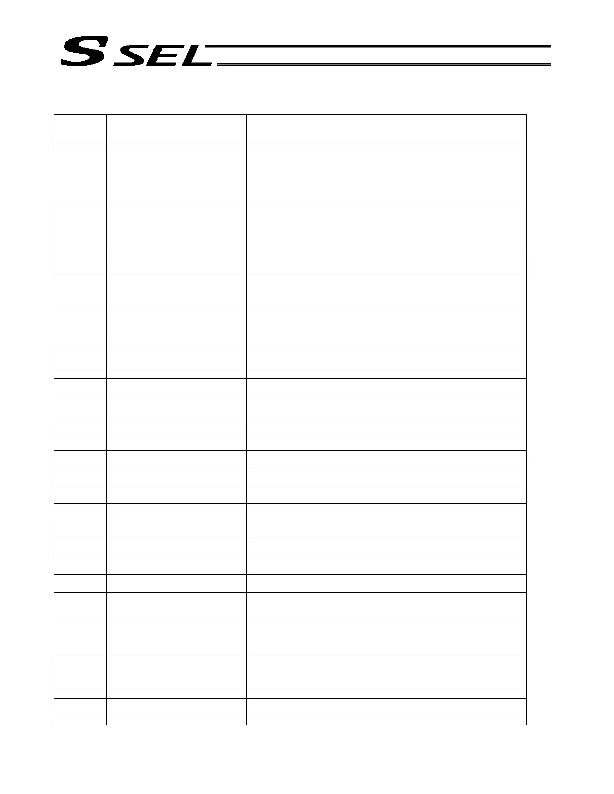
1.2 I/O Function Lists
(1) Input Function List
Input function
specification
value
Function name Remarks
0 General-purpose input
1 Program start signal
(BCD) (ON edge)
Specify a BCD program number using the ports to which start-program number
specification bits x (input function specification values 9 through 15) are assigned.
* To ensure starting of the program, keep these bits ON for at least 100 msec.
* The following input functions cannot be assigned at the same time:
• Program start signal (BCD) (input function specification value = 1)
• Program start signal (BIN) (input function specification value = 2)
2 Program start signal
(BIN) (ON edge)
Specify a binary program number using the ports to which start-program number
specification bits x (input function specification values 9 through 15) are assigned.
* To ensure starting of the program, keep these bits ON for at least 100 msec.
* The following input functions cannot be assigned at the same time:
• Program start signal (BCD) (input function specification value = 1)
• Program start signal (BIN) (input function specification value = 2)
3 Soft reset signal (ON for 1 second) If the emergency-stop recovery type is set to “Operation continued,” enable the
soft reset signal (to ensure the specified operation cancellation method will work.)
4 Servo ON ON edge: Same as the all-valid-axes servo ON command
OFF edge: Same as the all-valid-axes servo OFF command (an interval of at least
1.5 seconds is required).
* The signal must be input when the actuator is not operating.
5 Auto-start program start signal ON edge: Start the program
OFF edge: Abort all operations/programs (excluding the I/O processing program
at operation/program abort)
* Turn ON the signal for at least 100 msec to ensure starting of the program.
6 Soft interlock for all servo axes
(OFF level)
Effective when the servo OFF command is not active. Operations will be put on
hold if the interlock signal is input during auto operation. Operations will be
aborted if the interlock signal is input during non-auto operation.
7 Operation-pause reset signal (ON edge)
8 Operation pause signal (OFF level) Effective only during auto operation.
* Pause is reset using the operation-pause reset signal.
9 Start-program number specification bit 1
(least significant bit)
* Start-program number specification bits x (input function setting values 9 through
15) cannot be assigned discontinuously from the LSB or in descending order from
the LSB (port numbers are not considered). Program No. 1 (BIN or BCD)
10 Start-program number specification bit 2 (Same as “Input function specification value = 9”) Program No. 2 (BIN or BCD)
11 Start-program number specification bit 3 (Same as “Input function specification value = 9”) Program No. 4 (BIN or BCD)
12 Start-program number specification bit 4 (Same as “Input function specification value = 9”) Program No. 8 (BIN or BCD)
13 Start-program number specification bit 5 (Same as “Input function specification value = 9”) Program No. 16 (BIN) or 10
(BCD)
14 Start-program number specification bit 6 (Same as “Input function specification value = 9”) Program No. 32 (BIN) or 20
(BCD)
15 Start-program number specification bit 7 (Same as “Input function specification value = 9”) Program No. 64 (BIN) or 40
(BCD)
16 Error reset (ON edge)
17 Drive-source cutoff reset input (ON edge)
(Effective when the problem factor has
been removed)
Drive-source cutoff control is not available for axes whose motor-drive power
source is not installed in this controller, or axes whose drive-source cutoff circuit is
not controlled by this controller.
18 Home return command signal for all
valid axes (ON edge)
The servo must be turned on first (Input function specification value = 4, axis-
specific parameter No. 13)
19 Home return command signal for all
incremental axes (ON edge)
The servo must be turned on first (Input function specification value = 4, axis-
specific parameter No. 13)
20 PC/TP-servo movement command
acceptance permission input
* Caution: Ineffective once operation is started.
21 Remote-mode control input Is the specified DI is ON or the AUTO/MANU switch is set to “MANU,” the system
mode will become MANU.
* Debug filter is disabled on the remote-mode control input port.
22 Axis 1 forced brake-release input When the applicable port turns ON, the brake will be unlocked forcibly (pay
attention to falling load).
* Brake release of the synchronized slave axis conforms to brake release of the
synchronized master axis.
23 Axis 2 forced brake-release input When the applicable port turns ON, the brake will be unlocked forcibly (pay
attention to falling load).
* Brake release of the synchronized slave axis conforms to brake release of the
synchronized master axis.
24 ~ 27 For future expansion
28 Start-program number specification bit 8 (Same as “Input function specification value = 9”) Program No. 128 (BIN) or 80
(BCD)
29 Start-program number specification bit 9 (Same as “Input function specification value = 9”) Program No. 100 (BCD)

 Loading...


