EasyManuals Logo

IAI ssel User Manual

IAI ssel
497 pages
To Next Page IconTo Next Page
To Previous Page IconTo Previous Page
Page #33 background imageLoading...
Page #33 background image
7
Part 1 Installation
2. Name and Function of Each Part
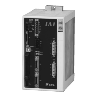
Front View
*1 For the 1-axis specification, [12], [14] and [16] are not installed and the front panel is masked.
[6] PIO connector
[4] MANU/AUTO switch
[5] USB connector
[11] Axis 1 motor
connector
[12] Axis 2 motor
connector
[13] Axis 1 brake-release
switch
[14] Axis 2 brake-release
switch
[1] LED indicators
[7] Panel unit
connector
[2] System I/O
connector
[3] TP connector
[8] Power connector
[9] Grounding screws
[10] Regenerative unit
connector
[15] Axis 1 encoder/
sensor connector
[16] Axis 2 encoder/
sensor connector

Table of Contents

Other manuals for IAI ssel

Questions and Answers:

Question and Answer IconNeed help?

Do you have a question about the IAI ssel and is the answer not in the manual?

IAI ssel Specifications

General IconGeneral
BrandIAI
Modelssel
CategoryController
LanguageEnglish

Related product manuals