22
Part 1 InstallationChapter 4 Name and Function of Each Part.
Part 1 Installation
(9) Teaching connector
The teaching interface connects IAI’s teaching pendant or a PC (PC
software) to enable operation and setting of your equipment from the
teaching pendant/PC. The physical interface consists of a RS232C
system based on a 25-pin, D-sub connector. The signal level conforms to
RS232C, and a desired baud rate (up to 115.2 kbps) can be selected
depending on the program. RS232C communication is possible only when
the mode switch (12) is set to the MANU position.
You can also use an ANSI teaching pendant equipped with an ANSI-
compliant double-action enable switch. Whether the controller supports an
ANSI teaching pendant or IAI’s standard teaching pendant can be set
using the selector switch (8) provided above the teaching connector. (P/PCT
type only)
* With a Q/QCT type controller, connect the supplied dummy plug to the
teaching connector in the AUTO mode.
* Q/QCT type controllers connot be used with IAI’s standard teaching pendants
and standard personal computer cable (black).
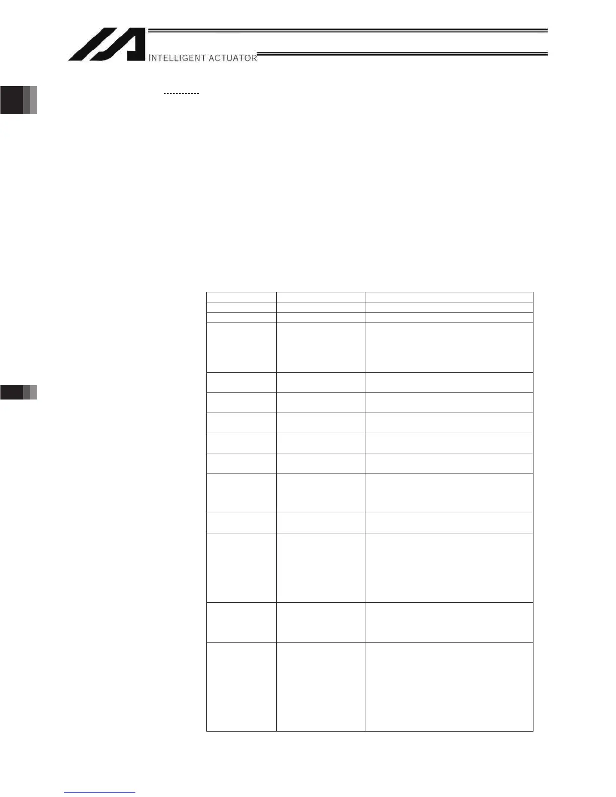
ecafretnIlaireSgnihcaeTfosnoitacificepSecafretnI
Item Description Details
Connector DSUB-25 XM3B-2542-502L (by Omron)
Connector name T.P. Teaching connector
Communication
method
RS232C-compliant,
start-stop
synchronous half-
duplex
communication
Signal assignments conform to the
RS232C DTE terminal layout. Assign
dedicated control lines to undefined lines,
etc.
Baud rate Up to 115.2 kbps Half-duplex communication speeds of up
to 115.2 kbps are supported.
Maximum wiring
distance
10M At 38.4 kbps
Interface
standard
RS232C
Connected unit Dedicated teaching
pendant
IAI’s standard teaching pendant for XSEL,
or ANSI teaching pendant
Connection
cable
Dedicated cable
Power supply 5 VDC or 24 VDC A multi-fuse (MF-R090) is installed to
protect each line against short current (the
fuse will trip with currents of between 1.1
A and 2.2 A).
Protocol XSEL teaching
protocol
The connector supports the XSEL-J/K
teaching pendant interface protocol.
Emergency-stop
control
Series emergency-
stop relay drive (24
V)
An emergency-stop relay drive line is
provided in the interface connector. This
line is connected in series with other
emergency-stop contact.
Two independent emergency-stop input
circuits are provided as a redundant safety
design.
Enabling control Enable switch line
(24 V)
A line for connecting an enable switch is
provided as an operator interlock. Two
independent enable input circuits are
provided as a redundant safety design.
(12) Mode
switch
AUTO/MANU switch Whether or not the teaching pendant can
be used is set by the AUTO/MANU mode
switch.
The controller establishes a handshake
with the teaching pendant only when this
switch is set to the MANU mode. Note,
however, that the teaching pendant
displays the monitor screen regardless of
the AUTO/MANU setting.

 Loading...