54
Part 1 InstallationChapter 6 Safety Circuit
Part 1 Installation
2. Safety Circuit for P/PCT Type (Standard Specification) Controller
The P/PCT type controller has a built-in drive-source cutoff circuit just like IAI’s other controllers.
The drive-source cutoff circuit consists of a relay and conforms to safety category B. If your equipment must
meet a higher safety category, use the Q/QCT type (global specification) controller explained later.
The standard controller has a built-in drive-source cutoff circuit. Connect the control power supply and motor
power supply to the same power source and also turn on/off the control power supply and motor power supply at
the same time.
The teaching port can be connected to either an IAI’s standard teaching pendant or ANSI teaching pendant.
Note, however, that redundant safety circuits cannot be configured even if an ANSI teaching pendant is used.
Set the teaching-pendant type switch located above the teaching connector to the position appropriate for the
teaching pendant used. Set the switch to the left for an ANSI teaching pendant, or to the right for IAI’s standard
teaching pendant.
Note: If the teaching-pendant type switch is not set properly, the safety gate switch will not function.
The emergency-stop line and enabling line are driven by the controller’s internal power supply. It should
be noted that the safety circuit cannot be driven by an external power source.
Do not use the internal power supply provided for the system I/O connector, for any other purpose. It
may damage the equipment or cause it to malfunction.
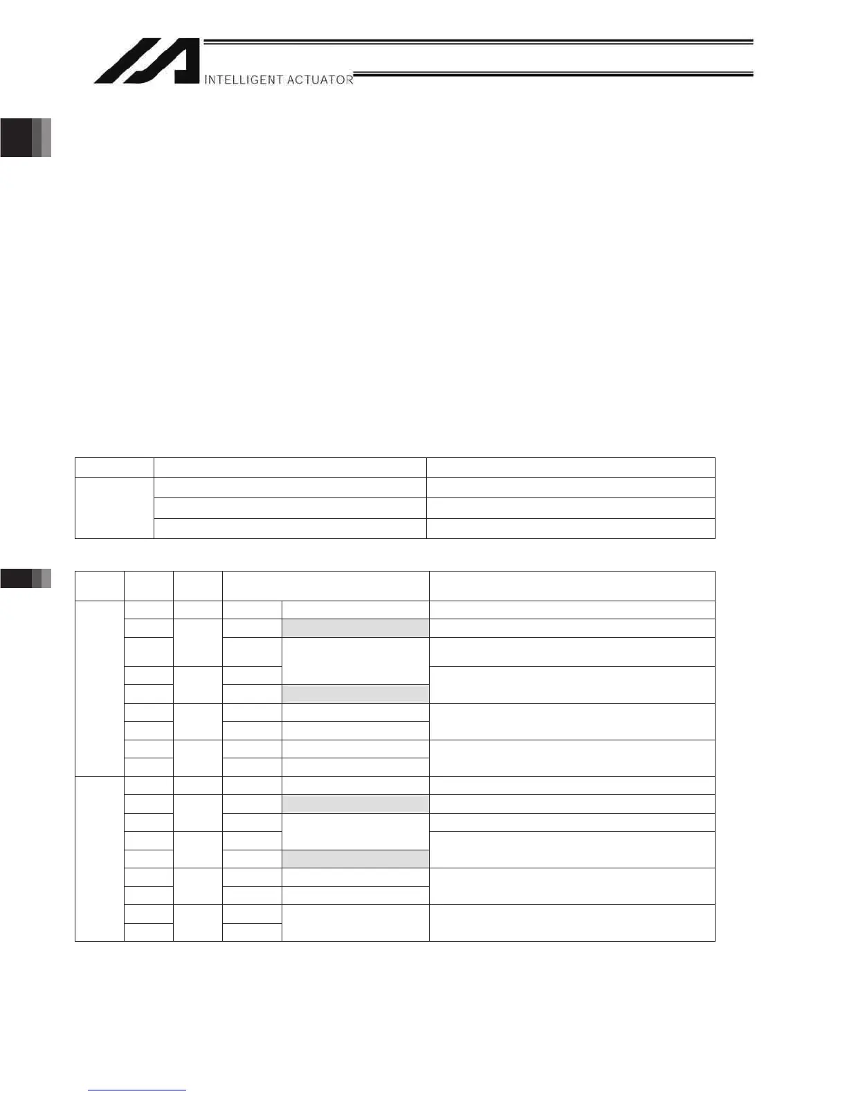
The tables below list the signals and wiring methods of the safety-circuit interface connector.
System I/O Connector for P/PCT Type
weivrevOmetI Details
COMBICON (2-row, 9-pin) MCD1.5/9-G1-3.5P26THR (by Phoenix Contact)
Cable-end connector FMC1.5/9-ST-3.5
Connector
61ot42GWAeziseriwelbacilppA
Terminal Assignments
Pin No.
Signal
name
sliateDweivrevO
9 DET IN Not connected Not used
8INTo external EMG Emergency-stop detection input
7
EMGin
+24V
24-V power output for emergency-stop detection
input
6 line+
Shorted
Wired before shipment
5
EMG1
line- To external EMG
Emergency-stop switch 1
Wire circuit 1 connected to EMG of the TP
4 line+ Not connected
3
EMG2
line- Not connected
Not used
2 Out+ Not connected
Left
1
SDN
Out- Not connected
External relay drive cutoff contact outputs
18 DET +24V Not connected Not used
17 IN To external ENB Enable detection input
16
ENBin
+24V 24-V power output for enable detection input
15 line+
Shorted
Wired before shipment
14
ENB1
line- To external ENB
Enable switch 1 (safety gate, etc.)
Wire circuit 1 connected to ENB of the TP
13 line+ Not connected
12
ENB2
line- Not connected
Not used
11 Out+
Right
10
RDY
Out-
May be used if
necessary
Ready signal contact outputs (dry contacts) (for
inductive load of up to 200 mA)

 Loading...


