1
Introuduction
Introduction
Thank you for purchasing the XSEL Controller.
Inappropriate use or handling will prevent this product from demonstrating its full function and may even cause
unexpected failure or result in a shortened service life. Please read this manual carefully, and handle the product
with due care and operate it correctly. Keep this manual in a safe place and reference relevant items when
needed.
The controller types covered by this manual are listed below.
Type Specification
labolGXSEL-Q/QCT
(Note)
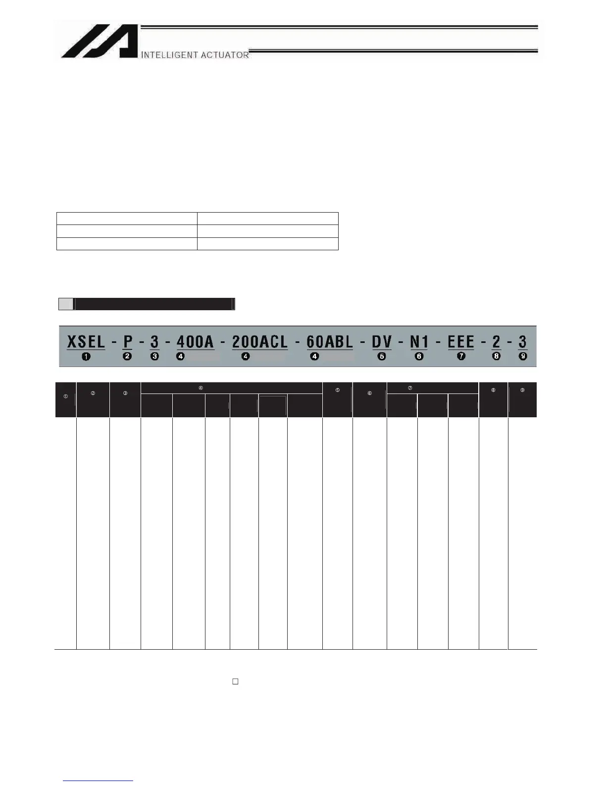
Refer to the following table for details on type specification.
Type
Example of type specification
Type specification table
Details of axis 1 to axis 6 Expanded-I/O slot
Series
Controller
type
Number of
axes
Motor
output (W)
Encoder
type
Brake
Creep
sensor
Home
sensor
(LS)
Synchro
specification
Network
(dedicated
slot)
Standard I/O
(slot 1)
Slot 2 Slot 2 Slot 2
I/O flat
cable
length
Power-
source
voltage
XSEL
P
(Standard)
Q
*1
(Safety-
category
compliant)
PCT㧦
Dedicated for
CT4
(Standard)
QCT
*1
㧦
Dedicated for
CT4
(Safety-
category
compliant)
1
(1 axis)
2
(2 axes)
3
(3 axes)
4
(4 axes)
5
(5 axes)
6
(6 axes)
12
(12W)
30D
(30W for
DS)
30R
(30W for
RS)
60
(60W)
100
(100W)
150
(150W)
200
(200W)
300
(300W)
400
(400W)
600
(600W)
750
(750W)
I
(Incremental)
A
(Absolute)
G
(Quasi-absolute)
Blank
(No
brake)
B
(With
brake)
Blank
(No creep
sensor)
C
(With
creep
sensor)
Blank
(No home
sensor)
L
(With
home
sensor)
Blank
(No synchro)
M
(Master axis
specification)
S
(Slave axis
specification)
Blank
(Network
not
available)
DV
(DeviceNet
256/256
board)
CC
(CC-Link
256/256
board)
PR
(ProfiBus
256/256
board)
ET
(Ethernet
Data
communica-
tion board)
E
(Not used)
N1
(Input 32/
Output 16
NPN board)
N2
(Input 16/
Output 32
NPN board)
N3
(Input 48/
Output 48
NPN board)
P1
(Input 32/
Output 18
PNP board)
P2
(Expanded
I/O
PNP16/32)
P3
(Input 48/
Output 48
PNP board)
E
(Not used)
N1
(Expanded
I/O
NPN32/16)
N2
(Expanded
I/O
NPN16/32)
N3
(Multi-point
I/O
NPN48/48)
P1
(Expanded
I/O
PNP32/16)
P2
(Expanded
I/O
PNP16/32)
P3
(Multi-point
I/O
PNP48/48)
S
*5
(Expanded
I/O with
base)
E
(Not used)
N1
(Expanded
I/O
NPN32/16)
N2
(Expanded
I/O
NPN16/32)
N3
(Multi-point
I/O
NPN48/48)
P1
(Expanded
I/O
PNP32/16)
P2
(Expanded
I/O
PNP16/32)
P3
(Multi-point
I/O
PNP48/48)
S
*5
(Expanded
I/O with
base)
E
(Not used)
N1
(Expanded
I/O
NPN32/16)
N2
(Expanded
I/O
NPN16/32)
N3
(Multi-point
I/O
NPN48/48)
P1
(Expanded
I/O
PNP32/16)
P2
(Expanded
I/O
PNP16/32)
P3
(Multi-point
I/O
PNP48/48)
S
*5
(Expanded
I/O with
base)
2: 2 m
(Standard)
3: 3 m
5: 5 m
0: None
2: Single-
phase, 200
V
3: Three-
phase,
200 V
*1 With this type, a safety protection circuit can be configured by separating the motor drive source.
*2 RCS2-R**7 series, RCS-RB75 series, RCS-G20, RCS-R* and linear motor (LCA) actuators cannot be connected as axes 5 and 6.
*3 One large high-thrust linear actuator (W21H
) occupies the space of two axes with one axis, so pay attention to the total number of
axes.
*4 [3] indicates the number of connected axes regardless of whether or not the condition in *3 applies.
*5 S indicates that an expanded I/O board will be added later, instead of being installed from the beginning. In this case, the applicable
expanded I/O base slot becomes empty.
(Axis 1)
(Axis 2) (Axis 3)
StandardXSEL-P/PCT
(Note)
Note
ޓ
XSEL-PCT and XSEL-QCT are dedicated for CT4 Actuator.
For other actuators, use XSEL-P or XSEL-Q.
*4
*2, *3
(*1)

 Loading...


