446
Appendix
Appendix
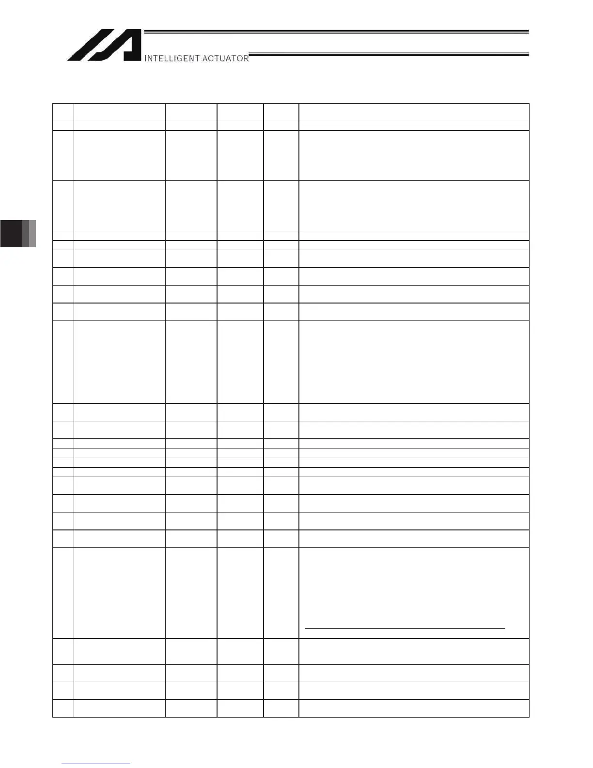
3. Axis-Specific Parameters
No. Parameter name
Default value
(Reference)
Input range Unit Remarks
1 Axis operation ty 0 0 to 1 0: Linear movement axis, 1: Rotational movement axis (Angle control)
2 $&0;DFFHOHUDWLRQ 30 1 to 999 0.01G Acceleration speed when ACMX Command is executed.
• Acceleration of movement in positive direction of the cooperate system
• Deceleration of movement in negative direction of the cooperate system
Setting is established based on transported weight, installation condition,
etc.
(XSEL-P/Q/PCT/QCT main application Ver. 1.15 or later)
3 ACMX - acceleration 1 30 1 to 999 0.01G Acceleration speed when ACMX Command is executed.
• Acceleration of movement in negative direction of the cooperate system
• Deceleration of movement in positive direction of the cooperate system
Setting is established based on transported weight, installation condition,
etc.
(XSEL-P/Q/PCT/QCT main application Ver. 1.15 or later)
4 $&0;DFFHOHUDWLRQ 30 1 to 999 0.01G Same as Each Axis Parameter No.2
5 ACMX - acceleration 2 30 1 to 999 0.01G Same as Each Axis Parameter No.3
6 Coordinate/physicaloperation
direction selection
1 0 to 1 0: Motor CCW Positive direction on the coordinate system
1: Motor CCW Negative direction on the coordinate system
7 6RIWOLPLW 50000 -99999999 to
99999999
0.001 mm Fixed to 359.999 degrees internally in the index mode. Invalid in the infinite-
stroke mode.
8 Soft limit – 0 -99999999 to
99999999
0.001 mm Fixed to 0 degree internally in the index mode. Invalid in the infinite-stroke
mode.
9 Soft-limit actual position
margin
2000 0 to 9999 0.001 mm Actual position margin in the positioning boundary critical zone in the
infinite-stroke mode
10 Home-return method 0 0 to 5 0: earch Z-phase after end search
1: Current position 0 home (This parameter can be specified only with an
incremental encoder. Pay attention to contact.)
2: Current position = Preset home (This parameter can be specified only
with an incremental encoder. Pay attention to contact.)
3: Automatically refresh home preset value and move to reference
coordinate after end search
* Valid only for ball-screw spline linear movement axes.
* Related information: Axis-specific parameter Nos. 10, 12, 141
(Main application version 0.82 or later)
11 Home-return end-search
direction selection
0 0 to 1 0: Negative end of the coordinate system
1: Positive end of the coordinate system
12 Home preset value 0 -99999999 to
99999999
0.001 mm (Refer to axis-specific parameter No. 76)
13 SIO/PIO home-return order 0 0 to 16 Executed from the smallest one.
14 Home-sensor input polarity 0 0 to 2 0: Do not use, 1: Contact a, 2: Contact b
15 Overrun-sensor input polarity 0 0 to 2 0: Do not use, 1: Contact a, 2: Contact b
16 Creep-sensor input polarity 0 0 to 2 0: Do not use, 1: Contact a, 2: Contact b
17 Initial home-sensor pull-out
speed at home return
10 1 to 100 mm/sec
18 Creep speed at home return 100 1 to 500 mm/sec End search speed in the creep-sensor non-detection section, if a creep
sensor is used
19 End search speed at home
return
20 1 to 100 mm/sec
20 Phase-Z search speed at
home return
3 1 to 10 mm/sec Exercise caution, since limitations apply depending on the read/encoder
pulse count.
21 Offset travel distance at
home return
1000 -99999999 to
99999999
0.001 mm
Offset travel distance from the ideal phase-Z position (Positive value =
Applied in the direction of moving away from the end)
(Refer to axis-specific parameter No. 76)
* Note when an absolute encoder is used
If a value near an integer multiple of the phase-Z distance (including
an offset travel of 0) is set in this parameter, the servo will lock above
Z-phase when an ABS reset is performed, in which case the coordinate
may deviate by the number of phase-Z pulses.
Never set a value near an integer multiple of the phase-Z distance.
(Provide a sufficient margin relative to the amplitude of the servo system.)
22 Allowable phase-Z position
error check value at home
return
500 0 to 99999999 0.001 mm Minimum allowable distance between the end (mechanical or LS) and
Z-phase in a rotary encoder specification. Phase-Z search limit in a linear
encoder specification.
23 Phase-Z count per encoder
revolution
1 1 to 8 Only “1” can be set, in the case of an absolute encoder.
Invalid in the case of a linear encoder.
24 Push stop check time at
home return
700 1 to 5000 msec
25 Push stop check time at
positioning
500 1 to 5000 msec

 Loading...


