8
Part 1 InstallationChapter 3 Installation Environment and Selection of Auxiliary Power Devices
Part 1 Installation
3. Selection of Auxiliary Power Devices
This section provides selection guidelines for breakers, earth leakage breakers, contactors, surge absorbers and
noise filters that can be used with the AC power-supply line of the XSEL controller. These devices must be
selected by taking into consideration the power consumption, rush current and maximum motor drive current of
the controller.
(1) Power consumption
The table below lists the current capacities of the control power supply and motor power supply.
The power values of the control power supply are indicated by maximum loads. The power values of the motor
power supply can vary in accordance with the connected axes and load condition. The table lists the power
values of the motor power supply based on a load factor of 100%. Although a duty factor of 50% is
recommended in this manual, these values assume the maximum allowable performance of the controller. A
maximum motor current of three times the rated current may flow during high-acceleration operations. The table
below indicates the momentary maximum currents calculated as three times the corresponding rated currents.
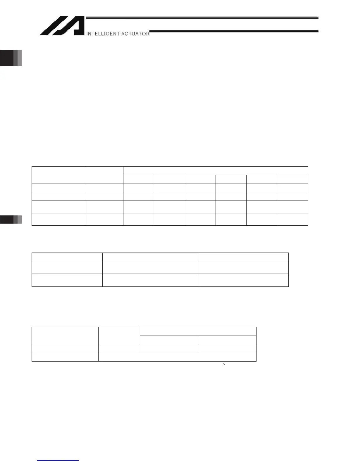
Guideline for AC Power-supply Operating Current
Motor power supply
Control power
supply
~ 400 W ~ 800 W ~ 1200 W ~ 1600 W ~ 2000 W ~2400 W
Rated power 181 VA 800 VA 1595 VA 2390 VA 3185 VA 3980 VA 4775 VA
Rated current 0.71 A 2.6 A 5.2 A 7.7 A 10.3 A 12.8 A 15.4 A
Momentary
maximum power
2400 VA 4785 VA 7170 VA 9555 VA 11940 VA 14325 VA
Momentary
maximum current
7.7 A 15.4 A 23 A 30.7 A 38.3 A 46.0 A
(2) Leak current
When installing the controller, always provide an inverter-type earth leakage breaker.
The table below lists the controller leak currents excluding the currents leaked from the servo system.
Model Leak current (control power supply) Leak current (motor power supply)
P/PCT type
(Standard specification)
Q/QCT type
(Global specification)
(3) Rush current
The table below lists reference rush currents that may generate in the control power supply and motor power
supply. As for the motor power supply system, the capacitor volume will vary depending on the number of driver
boards installed. However, the maximum current that can flow through the motor power supply remains the
same.
Motor power supply
Control power
supply
Less than 1200 W 1200 W or above
Rush current 50 A 60 A max.* 120 A max.*
Rush current duration 3 ms
*At40 C, 200-VAC input
0.2 mA (200-VAC input)
0.4 mA (200-VAC input) 2 mA max. (200-VAC input)
2 mA max. (200-VAC input)

 Loading...


