70
Part 1 InstallationChapter 7 System Setup
Part 1 Installation
Chapter 7 System Setup
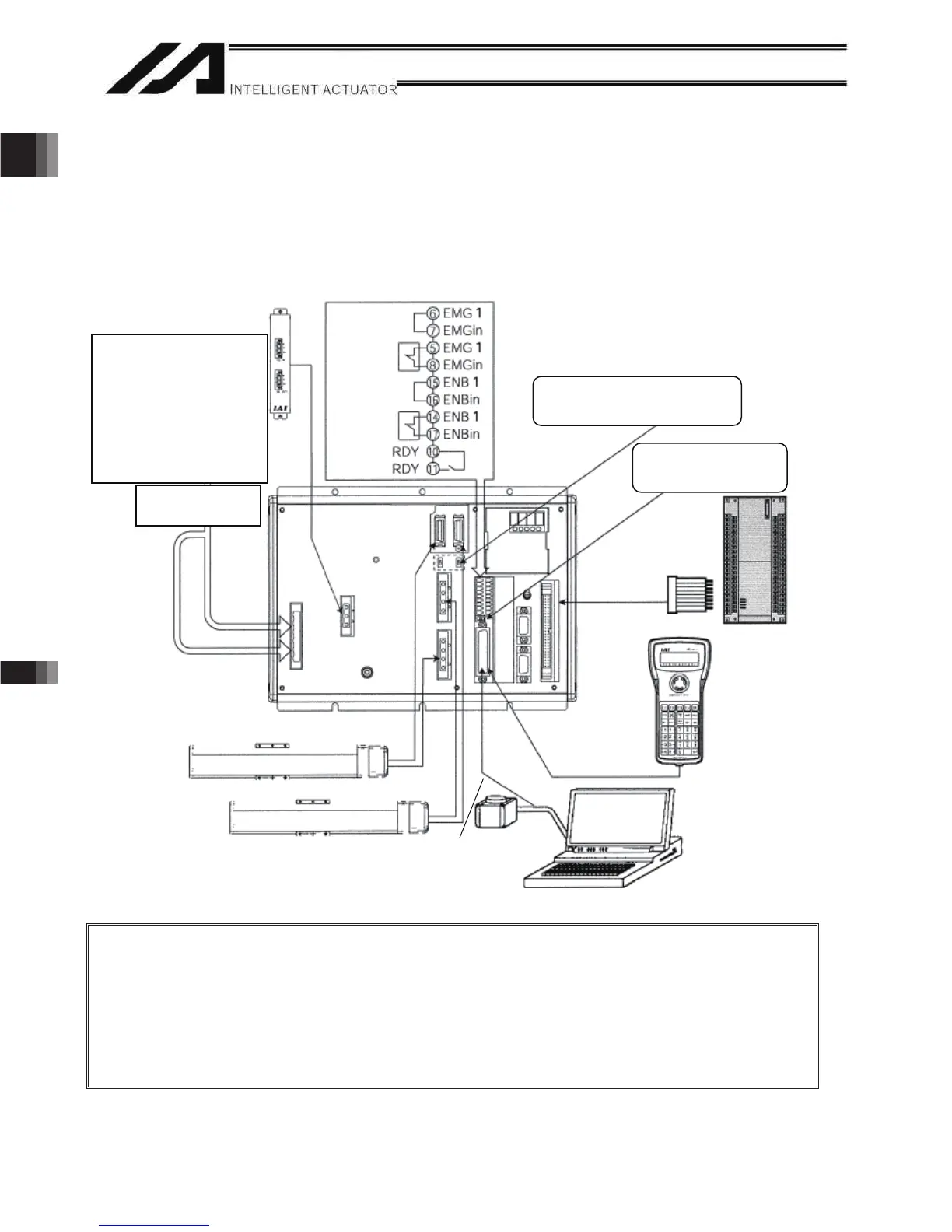
A connection example of a 2-axis controller is given below:
1. Connection Method of Controller and Actuator
In the case of an absolute specification, perform an absolute reset after the connection (refer to Chapter 8).
1.1 Connection Diagram for P/PCT Type (Standard Specification)
Note 1: With the absolute specification, set the absolute-data backup battery enable/disable switch
to the bottom position for all axes before connecting the encoder/axis-sensor cables. (After
the cables have been connected and power turned on, set the switch back to the top
position.)
Note 2: When connecting a teaching pendant or PC cable (PC software), set the teaching-pendant
type switch to an appropriate position.
Left: ANSI teaching pendant
Right: IAI’s standard teaching pendant or PC cable
Three-phase specification
CP: Single-phase, 200 to
230-VAC power source
MP: Three-phase, 200 to 230-
VAC power source
Single-phase specification
CP: Single-phase, 200 to
230-VAC power source
MP: Single-phase, 200 to
230-VAC power source
Auxiliary power
device circuit
Emergency-
stop switch
Enable
switch
Absolute-data backup battery
enable/disable switch
Teaching-pendant
type switch
Axis 1
Regenerative unit
(optional)
Host system
(PLC)
Teaching
pendant
(optional)
PC
Axis 2
PC connection cable
CB-ST-E1MW050
PC software IA-101-X-MW
ً
* CB-ST-A1MW050
cannot be used.

 Loading...


