Part 1 Installation
3. Power-Source Capacity and Heat Output
The power consumption and heat output of the XSEL controller will vary depending on the number of connected
axes and I/O configuration. This section explains how to estimate the power-source capacity and heat output of
your XSEL controller.
The XSEL controller requires the following power supplies:
A. Control power
Power to the logic control part of the controller. Single-phase 200 VAC must be supplied.
B. Motor power
Power for driving the actuator. Three-phase (single-phase) 200 VAC must be supplied.
* A single-phase power source is required only for controllers of single-phase specification.
C. I/O power
If a DIO card is installed in an I/O slot, 24 VDC must be supplied.
D. Supplemental power input (Power source to release brake and drive actuator)
It is necessary to supply 24V DC when connecting an actuator equipped with a brake or that recommended by IAI.
Recommended actuator (as of January, 2014): CT4 Pick & Rotary Actuator
(1) Power-source capacity and heat output
Rated power-source capacity [VA] = Motor drive power [VA]
*1
+ Control power-source capacity [VA]
*2
Heat output [W] = Total sum of output losses [W]
*3
+ (Heat output from control power supply [VA]
*4
x 0.7
(Efficiency) x 0.6 (Power factor))
*1 Select an appropriate motor drive power [VA] from Table 1. Note that during acceleration/deceleration, the
motor drive power increases by up to three times (or by up to twice if the motor wattage is 600 W or 700 W).
*2 Calculate the control power-source capacity [VA] by selecting the installed parts and then adding up the
power x quantity products of all installed parts according to the “Control power supply (Internal consumption,
External consumption)” fields of Table 2.
*3 Calculate the total sum of output losses [W] by selecting from Table 1 the output losses for all actuators to
be connected.
*4 Calculate the heat output from control power supply [VA] by selecting the installed parts and then adding up
the power x quantity products of all installed parts according to the “Control power supply (Internal
consumption)” and “External power supply (Internal consumption)” fields of Table 2.
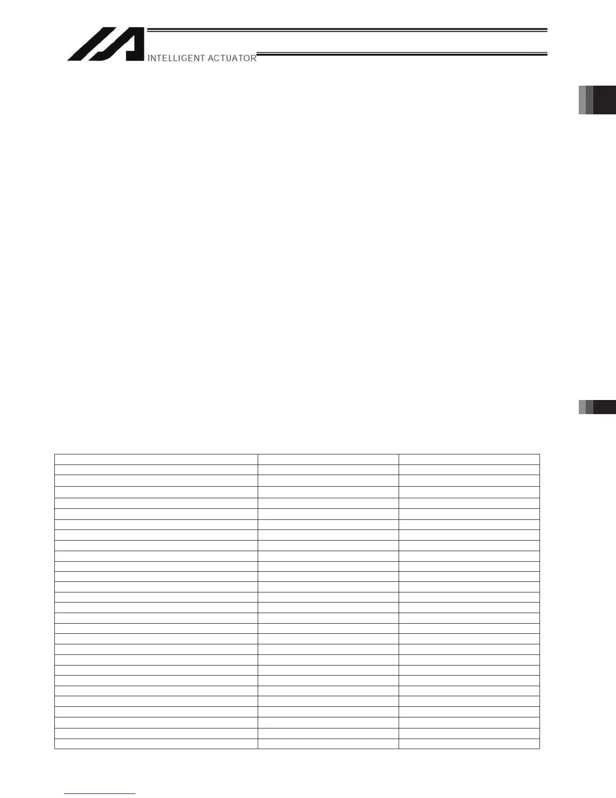
Table 1. Motor Drive Powers and Output Losses (P/Q/PCT/QCT Types)
Actuator motor capacity [W] Motor drive power [VA] Output loss [W]
85.16202
30D (other than RS)
70.264
30R (RS)
39.3831
39.383
197 3.6
7.5
10
60(RCS3-CTZ5C-□-60)
1230 18.0
400(RCS3-CT8C-□-400)
6
21.6432001
03.8823051
21.9124002
67.91697004
02.724611006
77.921251057
100 (LSA-S6S) 101 3.74
100 (LSA-S8S) 159 4.07
100 (LSA-S8H) 216 3.84
100S (LSA-N10S) 284 4.48
200 (LSA-S10S) 343 5.35
200 (LSA- H8S,L15S) 189 5.38
200 (LSA-H8H) 379 5.38
200S (LSA-S10H) 417 5.01
200S (LSA-N15S) 486 4.37
200S (LSA-N15H) 773 6.42
300S (LSA-N19S) 662 11.58
400 (LSA-W21S) 920 16.68
1000 (LSA-W21H) 1843 37.77
RS: Rotational axis / LSA: Linear actuator
DD Motor (LH18S, H18S)
DD Motor (LT18S, T18S)
1462
503
20.8

 Loading...


